The Forth Bridge – Railway Wonders of the World
 Published by the Amalgamated Press, Railway Wonders of the World appeared in 50 weekly instalments from 1st February 1935 through to 10th January 1936.
Part 14 of was published on Friday 3rd May 1935. and carried this “MARVELS OF ENGINEERING – 1” supplement
Spanning the Firth of Forth at a Cost of £3,000,000
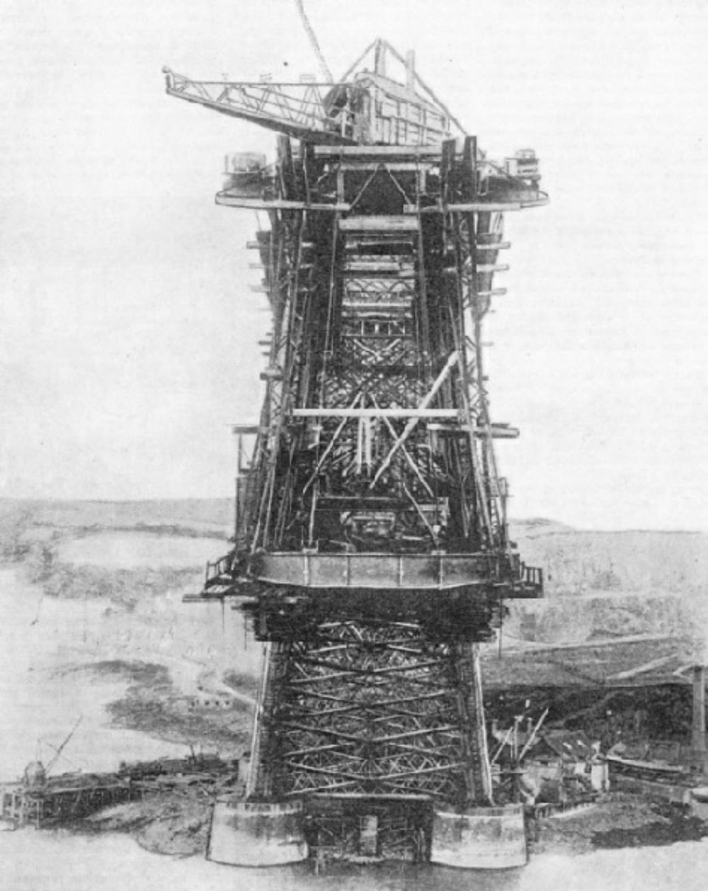 ONE OF THE GIANT CANTILEVERS of the Forth bridge during the early stages of its construction. Three cantilevers were built – one at the Queensferry shore of the Firth of Forth; another at the Fife shore; and a third on Inchgarvie Island. A glance at the ground level, and at the surrounding country, gives a vivid impression of the height of the cantilever.
MANY railway wonders cease to be wonders with the passing years. Improvements and inventions follow in quick succession. There are some things, however, which stand supreme, and among them is the Forth Bridge, which spans the storm-swept indentation on the East Scottish coast known as the Firth of Forth.
When railways began to grow and reached farther out until at last they offered the possibility of an east coast route between London and the northern centres of Scotland, this wide estuary offered a great obstacle to continuous communication. This way to the North runs via Newcastle and Edinburgh to Perth, Dundee, and points beyond. Before the bridging of the Forth a train-ferry plied across the estuary from Granton, Leith, to Burntisland, but this was inconvenient, slow, and uncomfortable. Travellers to Dundee, therefore, favoured the West Coast Route via Carlisle, because this way afforded direct communication.
An all-rail route did exist on the east coast, but it meant a detour of seventy miles via Stirling to reach Burntisland from Edinburgh, although the two points on opposite sides of the Forth are only about eight miles apart.
This put the East Coast Route at such a great disadvantage that the North British Railway Company, which was the system most vitally affected, set out to obtain direct railway communication across the estuary. The matter became imperative, owing to the acute competition of the West Coast Route. The urgency of some short cut across the waterway had been appreciated years previously, and both tunnelling and bridging schemes were outlined, discussed, and abandoned as impracticable.
In 1872, however, Sir Thomas Bouch advanced a proposal to bridge the Forth at the old Queen’s Ferry, which is familiar to readers of Sir Walter Scott’s novels. Bouch preferred this point because the Firth here is narrowed to one and a half miles, while in the middle of the estuary is the rocky islet of Inchgarvie. This engineer, who carried out the first Tay Bridge, evolved a startling proposal. His design contemplated a suspension bridge somewhat similar to the Clifton, Brooklyn, and other bridges of this type, with two spans, each of 1,600 ft in length. The engineer succeeded in satisfying his supporters of the possibility of such a bridge, and the requisite parliamentary sanction was obtained in 1873. To carry out the work the Forth Bridge Company was formed, with a capital of £1,666,666. The contract was secured by a well-known engineering firm; but, unfortunately, several delays arose, which postponed the start of the work until 1879. At the time these delays were exasperating, but it but it was providential that they occurred. During the stormy night of Sunday December 28, 1879, the central part of Bouch’s other great work, the Tay Bridge, fell into the Tay while a passenger train was crossing from shore to shore. Of the seventy-two people on the train not one escaped.
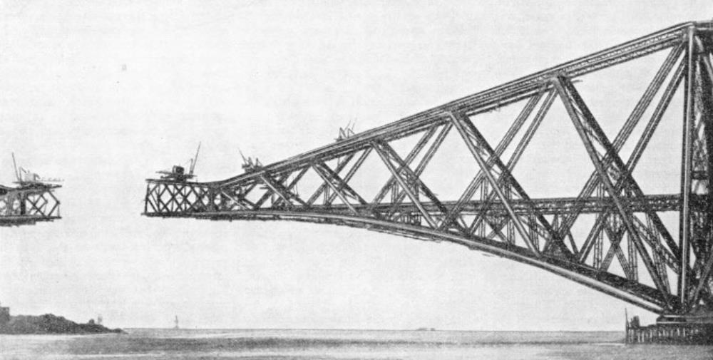 CLOSING THE GAP. The mighty arm of a cantilever, stretching into mid-air, is to be joined to another cantilever by a central girder 350 ft in length and 30 ft broad at the rail level.
The extent of this catastrophe and the details which were revealed as a result of the subsequent inquiry made public opinion antagonistic to Sir Thomas Bouch’s proposal for bridging the Forth. The Tay Bridge disaster, however, was not without its value, for had the Bouch Forth Bridge been built it would have come down with the first heavy north-easterly gale that blew along the Firth of Forth. He had allowed for a wind pressure of but ten pounds per square foot, an inadequate provision for such a structure as he proposed. The Board of Trade subsequently decreed that if such a bridge were undertaken it would have to be designed to withstand a wind pressure of fifty-six pounds per square foot on the surface of the side elevation of the bridge.
Spanning the Forth appeared to be in danger of becoming numbered among the apparently impossible things when the idea was revived by Mr. Matthew William Thompson, the chairman of the Midland Railway. Mr. Thompson was interested in the completion of the bridge, as his company worked a through service from London to Edinburgh by way of Carlisle and Galashiels and desired to extend it to Dundee and Aberdeen; a meeting of the directors of the North British, North Eastern and Great Northern railways (the three partners in the East Coast Route), and of the Midland Railway, was held at York to consider a co-operative proposal. The engineers of the four companies were requested to investigate the question. They did so, and, as a result, reported that the difficulty of bridging the Forth was not insuperable.
World-Wide Interest
They were invited to submit a design which they could recommend for adoption, and which would coincide with the requirements of the Board of Trade. Sir John Fowler, in collaboration with his colleague, Sir Benjamin Baker, drew up plans for a massive cantilever bridge.
In spanning the Firth of Forth due regard had to be paid to the claims of navigation, which were considerable. The significance of these claims is more obvious to-day, since a British naval base has been established at Rosyth. In the circumstances, a clear headway of 150 ft at high spring tides had to be allowed. The design comprised two spans, each 1,710 ft in length, two of 689 ft 9-in, and approach viaducts comprising fifteen spans of 168 ft, each resting on granite piers; four arch spans in granite, each of 57 ft, and three of 25 ft – practically one and a half miles in all.
The details of the design were examined thoroughly, and finally adopted as being the best possible solution of the problem. Sir John Fowler and Sir Benjamin Baker were appointed as the engineers to the undertaking. With much difficulty, and in the face of severe opposition, the requisite Parliamentary Act was obtained in 1882. At the end of that year the contract for erection was secured by Messrs. Tancred, Arrol and Co, a firm incorporated especially for this task.
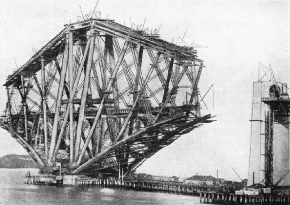 THE QUEENSFERRY CANTILEVER, photographed from the North British Railway during the construction of the Forth Bridge. Measured from its granite pier foundation, the arm of each cantilever is 680 ft long.
The construction aroused the keenest interest throughout the world, not only because of its immensity, but also because of the cantilever design which was adopted. The principle, however, is by no means new; in fact, next to the arch, it probably ranks as the oldest bridge-building principle in the world. Bridges of this character were common centuries ago in China, Tibet, and other little-known countries, while crude structures of this type have been thrown across yawning canyons among the mountains of North-West Canada by the Red Indians, though none of these ancients had such a material as steel, combining in outstanding degree properties of both strength and durability, with which to work.
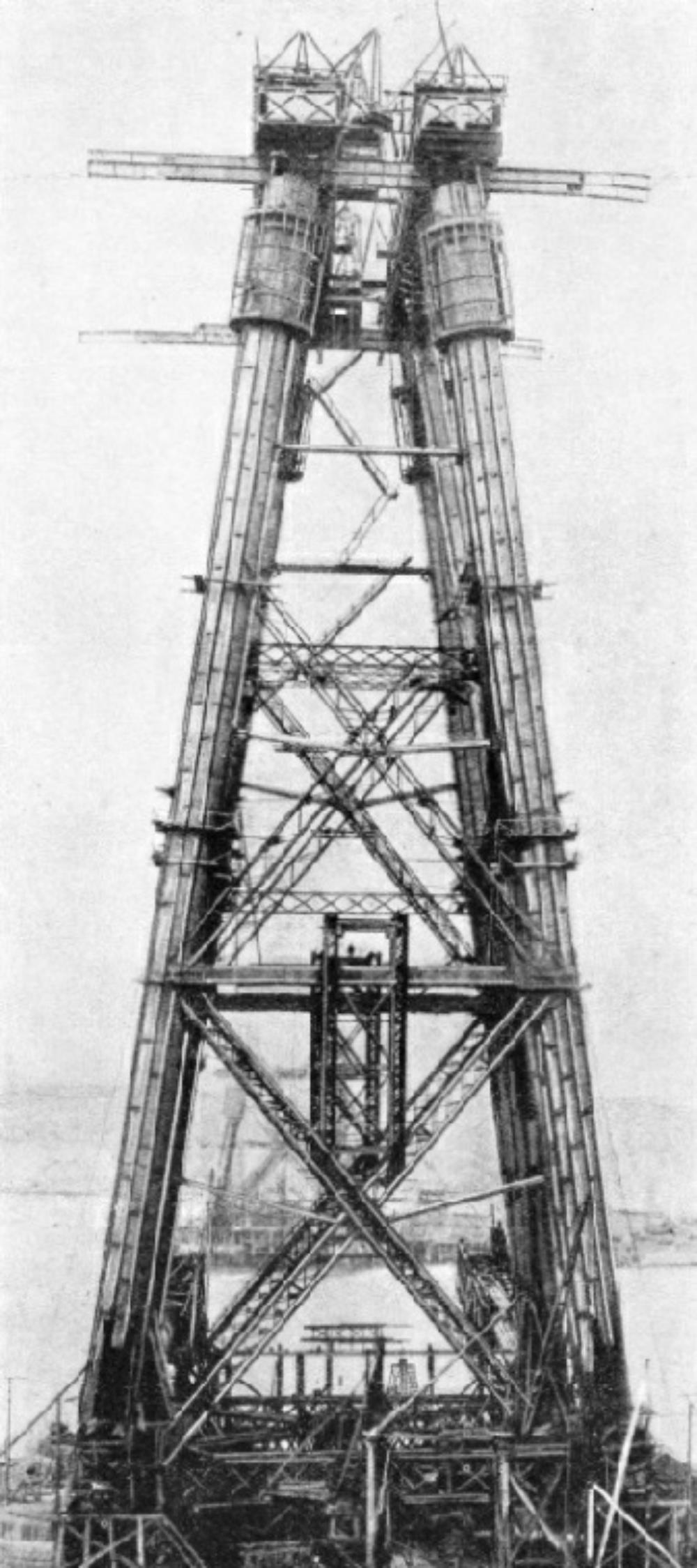 RISING TO THE SKY from its foundations. One of the vertical columns of the Queensferry cantilever. This column is 342 ft high. Each pair of cantilevers is able to support between them a girder span 346 ft 6 in long.
Not only did the new bridge eclipse anything previously attempted in the British Isles, but it was also more ambitious in its dimensions than anything hitherto completed in any other part of the world. In these circumstances the engineers were without precedents to guide them. The work was a pioneer work from beginning to end. Special devices, methods, and equipment had to be evolved to cope with unusual conditions, and awkward problems had to be faced practically every day.
The first move in construction was the erection of the approach viaducts, and at the same time the foundations for the cantilevers. The latter were placed respectively near the Queensferry and Fife shores, while the foundation of the central cantiIever was built on Inchgarvie Island. At each of these sites there are four cylindrical piers, and for the most part they were built upon the pneumatic caisson method. The sea bed varied from boulder clay on the Queensferry side to rock on Inchgarvie Island and the Fife bank. Iron caissons were built on shore, launched, towed out to the site, and lowered. Despite the size and weight of these caissons, and the difficulties experienced in handling them when afloat, they were sunk successfully with one exception. While the fourth caisson for the South Queensferry pier was being handled, it tilted slightly, permitting the water to enter through the rivet holes. As a result it became submerged, got out of control, and finally slid downwards on the mud. This was an unfortunate mishap; nine months elapsed before the caisson could be restored to the vertical position.
At the bottom of each caisson was a working chamber, 7 ft in height, where the excavators toiled, under compressed air. Admittance and exit were through the usual shafts and air locks. Owing to the character of the clay the caissons had to be sunk to depths ranging between 70 and 90 ft. At this depth the base of the piers is 70 ft in diameter, tapering up gradually to 60 ft at low water level; the shore piers are spaced 155 ft apart, and those on Inchgarvie Island 270 ft apart, from centre to centre. As the material was removed from the sea bed, it was sent aloft in skips through the shaft to be dumped into barges. Work was continued uninterruptedly in shifts throughout the twenty-four hours, and, on the average, from 200 to 300 skip loads were removed during a day by a force of from twenty to thirty men.
As the soil was excavated the caisson settled lower and lower under the weight of the super-imposed concrete until the requisite depth was gained. Then the air shafts were filled up and the upper work of the masonry was continued to the designed height above high water.
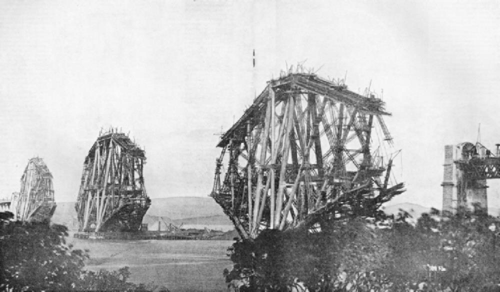 NEARING COMPLETION. A remarkable photograph of the three cantilevers. The Queensferry cantilever is in the foreground of the picture; the Inchgarvie cantilever is in the centre; and the Fife shore cantilever on the far bank of the Firth.
The lapse of time from the vertical columns attaining their full height to this stage of the work was nearly eighteen months. On the right of the picture can be seen the approach viaduct. When this photograph was taken, the distance to be covered before the southern arm of the Queensferry cantilever was linked with the viaduct was 240 ft. The viaduct has fifteen spans, each 168 ft long.
On Inchgarvie Island, as the sub-aqueous work had to be carried through rock to secure a level bench 70 ft below water, and as the caisson system was impracticable, owing to the slope of the rock, the base of the caisson was converted for the occasion into a huge diving-bell, 70 ft in diameter. As the men laboured in compressed air, a striking spectacle was often seen when the tide was falling. The water over the site became agitated and fussed like a boiling cauldron, owing to the pressure of the air within the working space of the caisson exceeding that of the head of water outside and accordingly securing its escape. These “blows” were a source of excitement and dismay to uninitiated visitors, who imagined that there was some terrible disaster among the drillers and blasters working 70 ft below the level of the river.
From the centre of each pier rises a gigantic tube, or leg of steel, 12 ft in diameter, to a height of 342 ft, each broadside pair leaning inwards. Thus, at the base, looking through the length of the bridge, the tubes are 120 ft apart, but at the top they are 33 ft apart. At the base each sloping pair is connected by a horizontal tube of the same diameter, while at the top the ends are connected by a box lattice girder, which likewise is 12 ft in depth. Additional strength is imparted by two diagonals formed of tubes, 8 ft in diameter, thus imparting great strength to the deepest part of the cantilever.
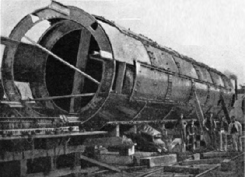 STEEL TUBES, 12 ft in diameter form the bottom member, or underside arm, of a cantilever. It is from this tube that the giant cantilever begins its 680 ft span of the Firth of Forth.
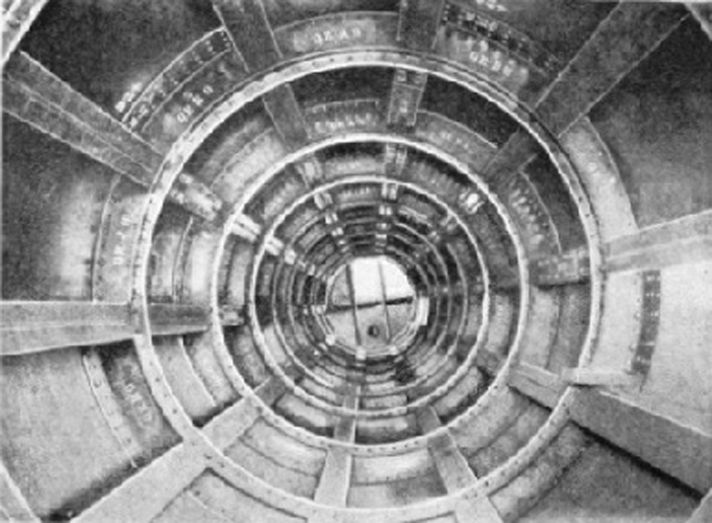 The interior of a tube.
From either side of this central section, or panel, the arm of the cantilever springs to a distance of 680 ft from the pier. Each bottom member of the arms comprises a steel tube, 12 ft in diameter, where it rises from the “skew-back” or bed-plate on the piers, and tapers to 5 ft in diameter at the extremity of its overhang. At the piers these two members are spaced 120 ft apart, but as they lean out over the water they draw gradually together until they are finally 31 ft 6-in apart. The top members, comprising a pair of box lattice girders, taper from 12 ft square at the pier to 5 ft at the outer extremities, while they likewise bear inwards from 33 ft apart at the piers to 22 ft 3-in at the ends.
As they descend in their outward reach the depth of the cantilever, which is 343 ft at the piers, decreases to 40 ft at the limit of the 680 ft overhang.
These top and bottom members of the cantilever are strengthened by tubes radiating from the piers in one direction like the ribs of a fan, and in the opposite direction by box lattice girders, so that a diagonal system of bracing is obtained. In addition to this longitudinal bracing there is an intricate system of transverse bracing, the steel lattice work being of an elaborate character. Looking broad-side at the bridge from a distance, it seems to be distinctly frail; but standing at one end of the bridge and looking through to the other, it appears to be an intricate maze of steelwork – so intricate, in fact, as to have prompted the remark that “one could not fire a bullet from a rifle across without hitting the steelwork somewhere”.
Except on those sides where the shore cantilevers reach out to join the approach viaducts, the overhang, 680 ft, is not sufficient to bring the arms together. The strength of the cantilevers is sufficient to enable each pair of cantilevers to support between them a girder span 346 ft 6-in long, 41 ft deep at the end and 51 ft deep at the centre, and weighing 872 tons. Each connecting span was built out from either end of the opposite cantilever arms, and the two halves were connected together 150 ft above high water. In this way the length of each span was increased by 346 ft 6 in without a proportionate increase in the length of the cantilevers themselves, and a corresponding economy in steelwork was secured.
Each cantilever is secured to its piers by, the aid of bed-plates. The upper part of each pier is provided with forty-eight steel bolts, 2½ in diameter, sunk to a depth of 26 ft in the masonry. These bolts received the lower bed-plates, which comprised five plates of steel held together by countersunk rivets. Upon these were superimposed four layers of steel, constituting the upper bed-plates. Each set of bed-plates has a weight of about 100 tons. Then the skew-back, some 40 ft in length, which unites in its grasp all the ten members of the cantilever, was riveted to the upper bed-plate.
Wind Pressure
As might be supposed, the unique character and size of this bridge demanded the most elaborate methods of building. Practically speaking, the bridge was built twice, first piecemeal at the works on shore and then on the site. The material was brought in its raw condition from the rolling mills to the contractors’ shops and fashioned to the required shape and design. Special machines were built to meet every phase of the work. Every piece was fitted to its neighbour on shore, and every rivet hole examined by the engineers before it was passed. If an additional rivet hole were considered necessary to make a sound job, the sanction of the engineers, who lived by the works, had to be obtained. Their assent was not granted until its necessity had become fully recognized and it was found that the metal would not be weakened in the slightest degree by such action.
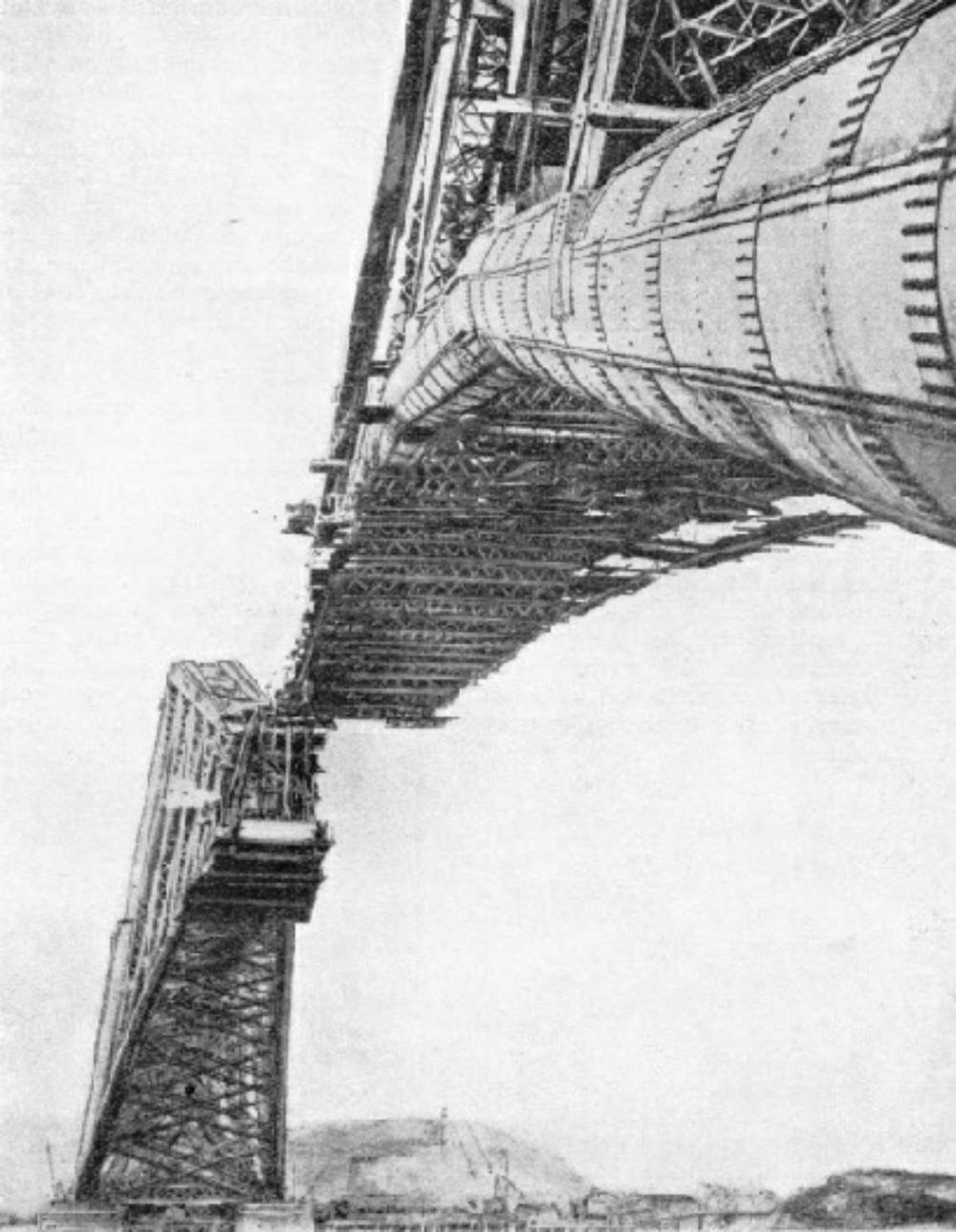 A REMARKABLE VIEW of the Forth Bridge showing the wind bracing – the steel latticework – that offers a minimum of resistance to wind pressure.
The engineers took no chances; they were resolved not to be taken unawares by the development of the unforeseen at an unexpected moment. It was these elaborate cautionary methods which enabled work to proceed steadily and persistently once it was begun, and which eliminated those periodical interruptions and hitches which often accompany undertakings carried out on this vast scale.
One instance of this decision to risk nothing may be related. At the time the work was in progress knowledge of the effect of wind pressure upon large bridges, the caprices of the wind, its action and, more particularly, its force in the Firth of Forth, was somewhat limited. On the island of Inchgarvie, which is exposed to the full brunt of a gale coming from the east, Sir Benjamin Baker set up some wind gauges, the records of which were observed carefully and frequently. One was of large size, measuring 20 ft by 15 ft. In the centre of this surface was placed another tiny gauge. On each shore more gauges were set up.
Some remarkable results were noticed. When the large gauge was registering a pressure of 12 lb per sq ft, it was found that the little gauge at the same time recorded as much as 25 lb per sq ft. This served to show that there is a tendency for the wind to act in the manner of a jet of water. At other times, when the Inchgarvie gauge registered a pressure of 34 lb per sq ft, the shore gauges would indicate anything from 12 to 22 lb per sq ft, proving conclusively that the strongest blows came in puffs, or are felt over only a comparatively small area.
The sum of these practical observations tended to show that the wind is more liable to have an adverse effect on a small than on a large bridge, because in the latter instance there is less likelihood of the whole structure becoming exposed at one time to the concentrated force of a powerful gust of wind. So far as the Forth Bridge is concerned, exposed as it is broad- side to the wind blowing through the Forth funnel, it is not likely to experience any ill effects, since, owing to the open character of the fabric, as compared with its transverse section, it offers a minimum of resistance to wind pressure.
The setting of the steel was carried out upon ingenious lines. Scaffolding was impossible. Work on the central section of each cantilever was carried out from the base to the top by means of a vertically travelling platform on which the handling machinery was placed. Cradles, or cages, were placed round the tubular columns for the riveters and their machines. The men were lifted and lowered by means of hoists and cages similar to those employed in mines, so that the minimum of time was lost in getting to and from the working areas, while the material was handled with relative convenience.
So successful were these arrangements that the centre portion of the Queensferry cantilever was built up to its full height of 281 ft above its pier in about twenty-four weeks. Similarly, in running out the bottom members of the cantilever a cage was erected round the outer end of the growing tube on which a crane was mounted, while the cage itself contained the riveting machinery and small special heating furnaces. This cage did not move along a track; but, as the tube advanced, the back part of the cage was dismantled and re-erected at the forward end, this procedure being repeated until the erecting work was completed.
Closing the Breaches
The task of connecting up the arms of opposing halves of a span in such a huge structure as this was extremely delicate. A mass of steel, 855 ft in length, which represents one-half of one of the great 1,710-ft spans, has a pronounced stretch under the action of the sun’s rays. The calculations necessary to enable connexion to be accomplished with the minimum of delay were made, and the closing lengths, or key pieces, were carefully prepared. A cloudy day, when the temperature was equable, was selected, and the breaches were closed without the slightest hitch. Moreover, the details were prepared in such a manner as to enable the key piece to be completed, and the temporary connexion to be cut away, in a few hours.
There was a keen rivalry among the workmen on the opposite ends of the meeting arms to be first across the gap. Two men decided to steal a march upon their fellow workmen, and one of these was resolved not to share the honours with anyone if he could help it. The only difficulty was that he could not get rid of his colleague.
Suddenly an idea occurred to him. They had a ladder that was just long enough to reach across the breach if only a rope could be obtained to lash it at one end. The second man, unsuspecting, hurried off to find a rope. His comrade, shouldering the ladder, then laid it across the jibs of the cranes working on the end of each arm. The ladder held, and he crawled across this dangerous gangway, some 200 ft above the water. The feelings of his companion when he returned with the rope and found what his friend had done may be imagined.
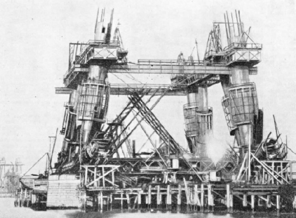 STEP BY STEP the vertical columns of the Queensferry cantilever each climbed to its height of 360 ft. As the height of these columns increased it became necessary to have a travelling platform, which could raise all the machinery together.
The railway tracks are laid on a viaduct that runs through the cantilevers. There is a double road, with a gangway on either side for workmen. The bridge was subjected to severely exacting tests in February, 1890, under direction of the Board of Trade, from which it emerged triumphantly, the maximum deflection on the ends of the cantilevers of the main spans being only 7¾-in and 1⅝-in at the central girders. The following day a furious gale swept the Firth of Forth, but the bridge stood as firmly as a rock. The official opening took place on March 4, 1890, when, King Edward VII, as Prince of Wales, drove the last rivet in the middle of the northern main girder.
By the time the structure had been completed £3,000,000 had been expended, of which the bridge proper absorbed about £1,700,000, the plant and general charges some £800,000, and the connecting roads of railway £500,000. Over 54,000 tons of steel were used in the work. The Inchgarvie piers support 18,700 tons, and the other two sets of piers 16,130 tons each. To hold this mass of steel together, about 6,500,000 rivets, representing 4,000 tons of steel, were required, and 40 miles of steel plates were used for fashioning the tubes. In addition, 740,000 cubic feet of granite masonry, 46,300 cubic yards of rubble masonry, 64,300 cubic yards of concrete, and over 21,000 tons of cement were utilized.
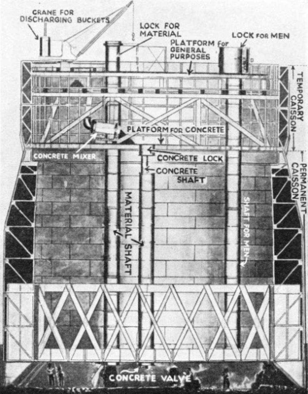 INSIDE A CAISSON. Caissons were sunk beneath the Firth of Forth to depths varying from 70 ft to 90 ft to form supports for the foundation piers. They were also used for excavating the bed of the river. At the bottom of each caisson was a working chamber, 7 ft in height, in which the excavators toiled under compressed air.
When work was in full swing an army of 5,000 men found employment; an elaborate system of precautions ensured that accidents were reduced to a minimum. The length of the three cantilevers, with their two connecting spans, adds up to exactly one mile. At the centre of each 1,710-ft span there is a headroom of 157 ft above high water, and the tops of the cantilevers are 361 ft above high-water mark – a figure practically equal to the maximum height of St. Paul’s Cathedral.
Yet, although the bridge is sufficiently strong to withstand a tornado, it is susceptible to the ravages of an implacable enemy – corrosion, and the more so by reason of its constant exposure to salt-laden air. In order to frustrate this attack the bridge has to be given a protective coat. This task is, in itself, one of considerable magnitude, seeing that the area of steelwork which has to be treated totals approximately 135 acres. The work has been in constant progress since the year 1883, and about three years are required to give the whole of the fabric one coat, at the conclusion of which painting immediately begins again at the opposite end. In accomplishing their work the painters, of whom 45 are employed regularly, use over 40,000 lbs of paint during the year, or about 54 tons for the whole structure.
Since the steel highway that carries the train is continuous for a length of 4,800 ft, there is a considerable movement of the metal under the variations of temperature. The total allowance for expansion and contraction is 8 ft 4 in, there being four expansion joints on each track over the cantilever sections.
For many years this wonder of engineering ingenuity and magnificent workmanship has withstood the stress of heavy traffic, wind and storm, yet not the slightest sign of weakness has been revealed. Most remarkable of all, perhaps, is the fact that a structure completed at a time when locomotives and tenders weighing not more than 75 tons were in use should to-day, with comparatively little strengthening of the railway track and its supports be carrying engines of 160 tons weight, and also proportionately heavier coaches and wagons.