Rosyth Dockyard 12 – 1914-1916 The Entrance Lock
| < 11 – 1914 Completing the Main Basin | Δ Index | 13 – 1916 The Entrance Pier / Coaling Station > |
The entrance lock was arguably the most complex part of the project. It had the largest moving parts, and was subject to the greatest range of hydraulic pressures.
The lock, which can also be used as an emergency dry dock, is 850 ft (259m) long and 110 ft (33.5m) wide at the entrances.
Each end of the dock is fitted with a gate in the form of a sliding caisson which fits into a caisson groove to seal the opening. To open the gate the caisson is drawn into an adjoining caisson “camber” by an electrically-powered winch. (In an emergency it can be winched manually!)
The entrance lock allows ships to enter or leave the inner basin at any state of the tide.
The sill (i.e. the bottom of the lock gate) at the basin end is at the same level as the floor of the inner basin, where water level is maintained at 38ft (11.6 m).
The floor of the entrance lock from just beyond the inner sill to the outer sill at the river end of the lock, is 13ft (4m) lower than the inner basin. This provides a depth of water of 36ft (11m) at low water spring tides – i.e. the lowest low tide. This allows ships to enter or leave the lock at any state pf the tide. Once a ship is inside the lock, the gates are closed and the water level in the lock is adjusted to match the basin or river level to allow the ship to enter or leave as required.
 The entrance lock in elevation, basin end on left, river end on right. This diagram shows how the floor of the lock steps down just beyond the inner sill
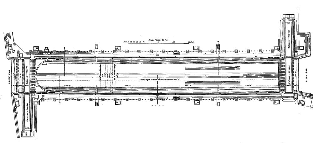
 Entrance lock plan showing the caisson grooves and caisson cambers at each end of the lock.
The basin end is on the left and the river end is on the right.
Note the curved end of the lock floor at the basin end. This is the step where the floor drops 13ft (4m) to match the depth of the outer sill (river end).
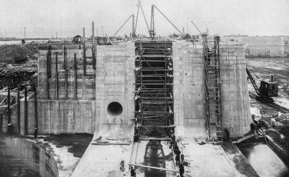
 The basin end caisson groove of the entrance lock, looking north – i.e. basin on the left. The curved edge on the right is the step where the floor drops by 13ft (4m) to match the depth of the outer sill at the river end of the lock.
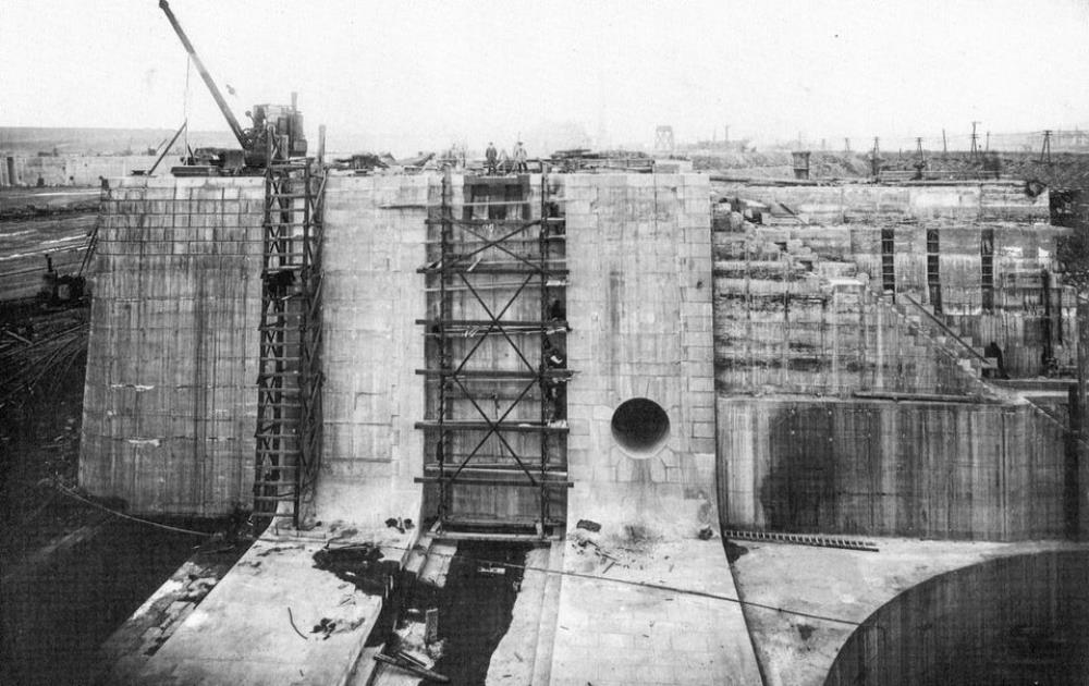
 The basin end caisson groove and caisson camber of the entrance lock, looking south – i.e. basin on the right. The camber holds the caisson when it is drawn aside to open the lock gate.
The holes in the wall adjacent to the caisson groove are the opening of the conduits which allow water to be pumped in and out of the lock.
An approach channel 1050ft (320m) wide for access to the lock was dredged to 38ft (11.6m) below low water spring tides.
Water levels at Rosyth in 1914
Datums and Tide Levels are explained in this Appendix
The tidal range in 1914 at Rosyth was as follows:-
MHWS Mean High Water Springs 8.75 feet above Ordnance datum.
MLWS Mean Low Water Springs 7.55 feet below Ordnance datum.
MHWN Mean High Water Neaps 5.15 feet above Ordnance datum.
MLWN Mean Low Water Neaps 3.40 feet below Ordnance datum.
The chart datum is 8.75 feet below Ordnance datum.
The water level in the basin is 6.34 ft (1.93m) above the Ordnance datum. This about the average high tide level –halfway between the highest high tide (High Water Springs or 8.75 feet) and the lowest high tide (High Water Neaps 5.55 feet). The floor of the basin is therefore dug out to a depth of (38 – 6.34) about 32 feet below Ordnance datum.
The sill of the inner or basin entrance to the lock is at the same level as the floor of the inner basin or 32 ft. below the Ordnance datum.
Before a ship enters the lock from the inner basin, the water level in the lock is adjusted to match the level in the basin. Once the ship is in the lock, the basin entrance is closed, and the water level in the basin is adjusted to match the current sea level (which would usually be lower than the level in the basin). The outer or river entrance is then opened and the ship can leave the lock.
The reverse process applies to a ship entering from the river. The water level in the lock is adjusted to match the current sea level. The outer caisson is opened. The ship enters the lock. The outer caisson is closed. Water is pumped in to the lock to match the level in the inner basin. The basin end caisson is opened and the ship can enter the basin.
The sill of the outer or river entrance is at 45 ft. (13.7 m) below the Ordnance Datum (O.D.), so it is 13 feet (4m) lower than the sill at the basin end. It therefore provides a water depth of (45 – 7.55) or 37.5 feet at MLWS – lowest low tide. So ships can enter or leave the entrance lock regardless of the state of the tide.
 Elevation through the entrance dock. The inner sill (basin end) is 32 ft below O.D.
The floor of the lock and the outer sill (river end) are 45 ft below O.D.
The entrance lock as an emergency dry dock.
If a severely damaged ship arrives at the dockyard, it may be drawing up to 10ft more than normal (if it is drawing any more it will sink!)
The inner basin is not deep enough to accommodate a ship in this conditions. But because the sill of the river entrance is 13 ft (4m) lower than the inner entrance, a damaged ship can enter the entrance lock at high tide, and the entrance lock can then be used as an emergency dry dock. Water is pumped out of the lock, so that temporary repairs can be made to the damaged ship to restore its normal draught. It can then proceed into the inner basin, for full repair in one of the normal dry docks.
Completion of the entrance dock – September 1916
At the start of the war, the channel through Dhu Craig rock for the entrance lock had been excavated, but construction of the floor and walls had not started, nor had the approach channel been dredged.
By September 2015, the walls and floor were in place along with the caisson cambers at each end.
Water pressure in dry docks and the entrance dock.
The lock gates of the graving docks in the inner basin must cope with a difference in pressure of 0 feet when full of water to 32 feet (9.75m) when pumped dry. This pressure is exerted horizontally on the base of the caisson, and vertically under the floor of the dock. If water can creep under the floor it can leak through a porous floor, or try to force its way through a solid floor, which must be strong enough to resist this pressure.
The base of No 1 dry dock sits on solid sandstone for its full length. The southern half of dock No.3 is on this same outcrop, but its northern half, and all of dock No.2 is built on sandy shale. These docks were provided with a thick concrete floor that would withstand the water pressure from below.
The entrance dock has to cope with a greater variation in water depth than the dry docks, because its floor and outer sill are 13ft (4 m) lower than the floor of the inner basin. The floor of the entrance lock has to cope with the pressure from a depth of water of 45 ft (13.7m) when it is used as emergency dry dock. It therefore needs a firm foundation and a very strong floor.
The inner basin was oriented to place the entrance dock across the site of the Dhu Craig rock at the south east of the inner basin. This provided a foundation of solid dolerite once a channel had been blasted through the rock. The resulting material was used as aggregate in the main concrete dock walls.
On 10th October 1915, the entrance lock was tested as an emergency dry dock. During pumping out, a part of the concrete floor was dislodged by water coming through fissures in the bedrock. Gibb had warned the Admiralty that their floor design was too thin, and now a more substantial replacement had to be constructed. This was completed on 16th February 1916.
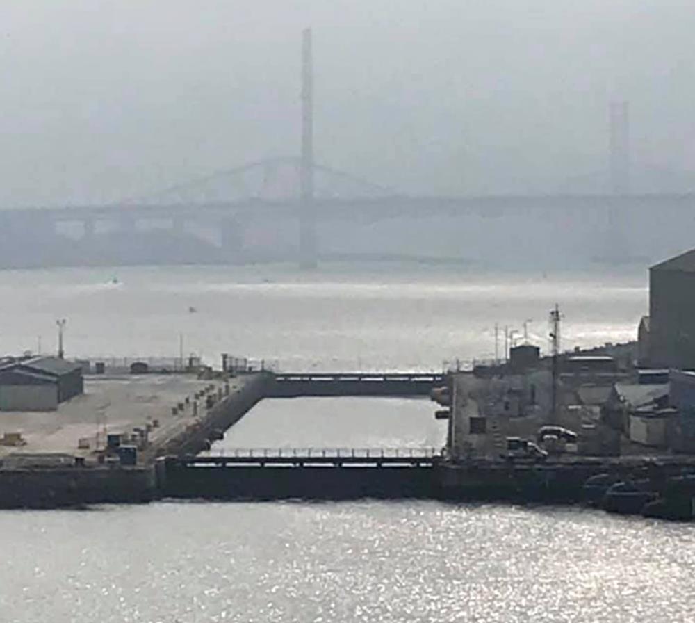
 A modern view of the entrance lock from the inner basin
| < 11 – 1914 Completing the Main Basin | Δ Index | 13 – 1916 The Entrance Pier / Coaling Station > |