Rosyth Dockyard 16 – 1916 Fitting the caissons to the entrances
| < 15 – 1915 Excavating the main basin | Δ Index | 17 – Caissons manufactured at North Queensferry > |
While Easton and Gibb were working on the main infrastructure, Armstrong, Whitworth and Company had built the pump machinery and William Arrol and Company of Forth Bridge fame had built the basin sluices and the caissons to seal the ends of the various docks.
There were a total of eight caissons required. Six of these were slab-sided sliding caissons – one for each of the three graving docks, one for the emergency entrance, and one for each end of the entrance dock.
One additional hull-shaped floating caisson would be used to subdivide graving dock No. 1 and another floating caisson was provided as a secondary caisson for the emergency entrance.
The four caissons for the graving docks were built on the railway pier at North Queensferry, then they were launched and pulled upstream to the dockyard by tugboats.
The four caissons for the entrance dock and the emergency entrance were built inside the main basin. When the basin was flooded to a depth of 39ft 6 inches the sliding caissons could be floated into position then their ballast tanks were opened and they settled into position. They could then seal off both ends of the entrance lock and the emergency entrance. The areas outside the main basin but still inside the temporary clay dams at the entrance lock and emergency entrance could then be pumped dry to allow finishing work to continue.
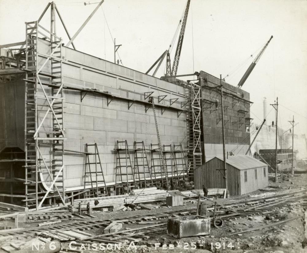 A sliding caisson under construction in the inner basin
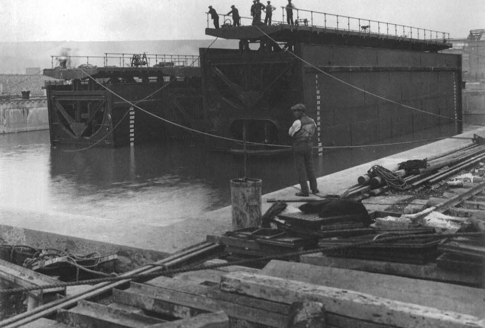 Sliding caissons afloat, ready to be moved to the appropriate caisson groove.
This diagram shows a cross section through a sliding caisson. At each end of the caisson there is a ballast tank with a capacity of 44 ½ tons of water. When this ballast tank is empty the caisson can float as shown here. It can then be manoeuvred into position above the caisson groove. . .
Easing the sliding caisson into position
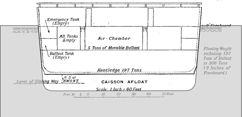 A sliding caisson afloat – it just clears the caisson groove at each end – the grey shaded area.
This diagram shows a cross section through a sliding caisson. At each end of the caisson there is a ballast tank with a capacity of 44 ½ tons of water. When this ballast tank is empty the caisson can float as shown here. It can then be manoeuvred into position above the caisson groove just clearing the end of the caisson groove in the dock wall and the mouth of the caisson camber because of the 1 in 12 batter at each end.
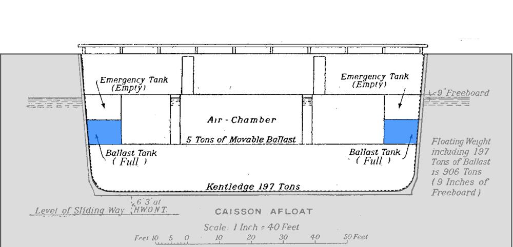
Once in position the ballast tanks can then be filled and the caisson will settle into position fitting snugly into the caisson groove.
The caisson is sealed against the caisson groove and camber with wooden beams. (Modern caissons used neoprene seals!)
Force needed to move a sliding caisson
The technically minded can read about the force necessary to move a sliding caisson in this Appendix
Folding decks on the caissons
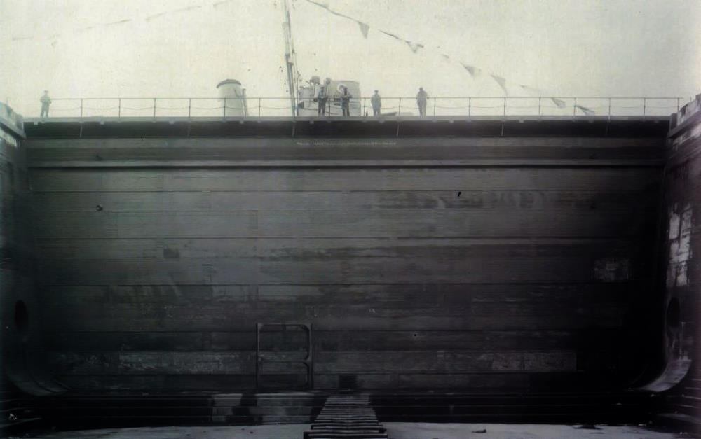 A sliding caisson in the closed position – note the railings and deckway on top.
When the caissons are closed, they form a deck with handrails across the end of each lock or the emergency entrance. This deck continues over the top of the caisson cambers. When the caisson is pulled into its camber, the deck and railings fold down automatically.
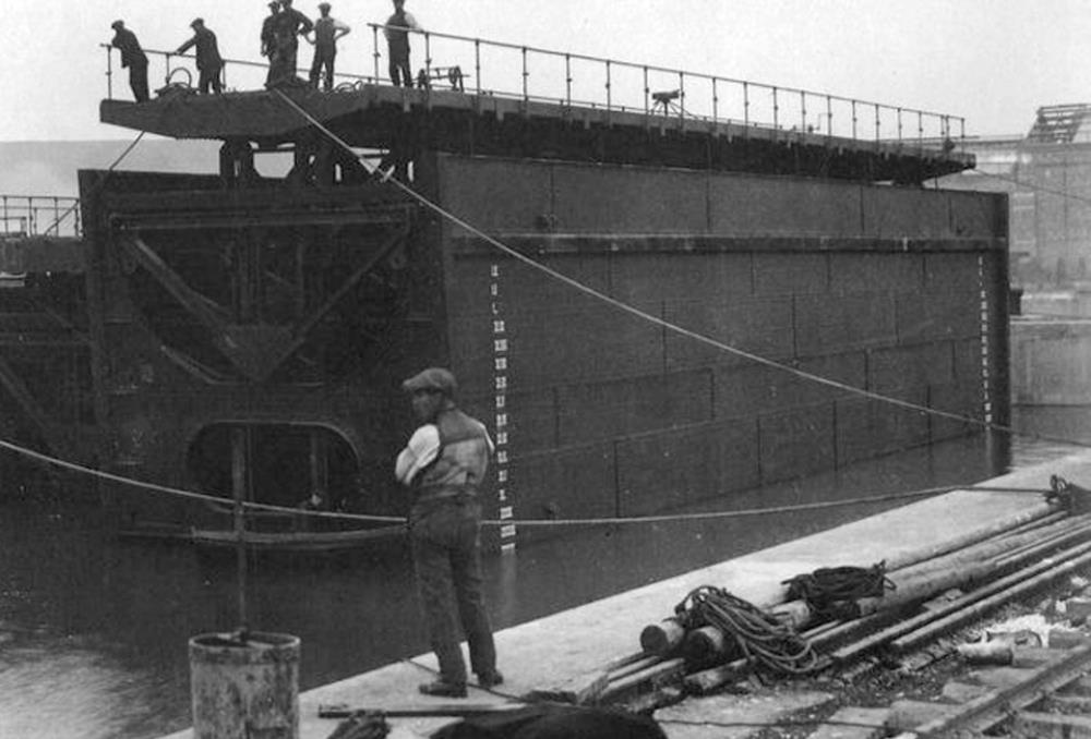 This photograph shows the top deck and railings which can fold down
| < 15 – 1915 Excavating the main basin | Δ Index | 17 – Caissons manufactured at North Queensferry > |