Appendix – The operation of the electrical equipment
| < back to Electrical Control of a Mine | Δ Index |
Battery, Switch, Fuse.
This diagram shows the three elements involved in firing a mine by electricity.
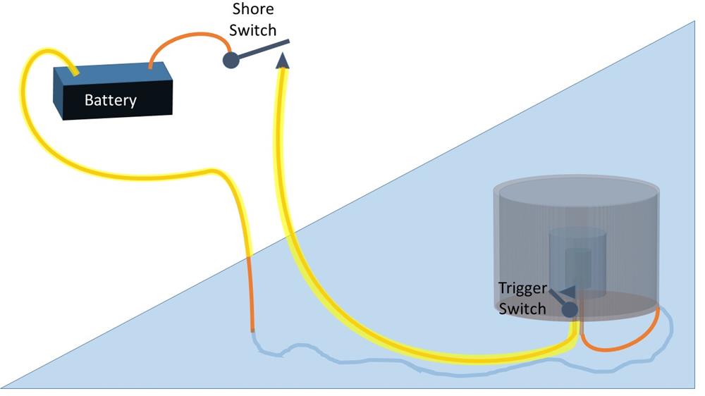
The mine contains a fuse which is heated by an electric current supplied by a battery in the shore station through an underwater cable. This current is turned on by closing a switch in the shore station if it is an observation mine, or by closing the trigger switch when a mine is bumped if it is an electro-contact mine.
In practice, additional equipment was needed to allow the mines to be tested as they were being installed, and on a daily basis to ensure that the connections had not been damaged by passing friendly ships.
This details of the equipment evolved over time, but the general principles remained the same.
It was initially thought useful to have one combined circuit-closer and observation mine. However a later invention allowed multiple circuit-closer mines to be connected to one cable, which made deployment faster and more economical.
Combined Observation and Circuit-Closer Mines
Here is the set up for the early combined observation and circuit-closer mine. It consists of:
1. A low-voltage signalling battery, a high-voltage firing battery, and a multi-cell low voltage test battery (in the shore station)
2. A circuit closer – a trigger switch in the mine which was activated by vibration, i.e. something striking the mine.
3. The fuse which detonated the mine.
4. A test galvanometer – an instrument which measures electrical current flowing in a wire
5. A “wooden relay” inside the mine that verified the electrical connection
6. A shutter box – a shore station instrument connected to each mine which indicated that the mine had been struck (the trigger switch had been activated) and if the firing battery was connected would detonate the mine
7. A sturdy single-core cable connecting each mine to the shore station.
8. A switch board or set of plugs and sockets that allowed the various items to be connected in different configurations.
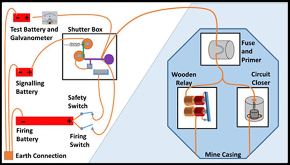
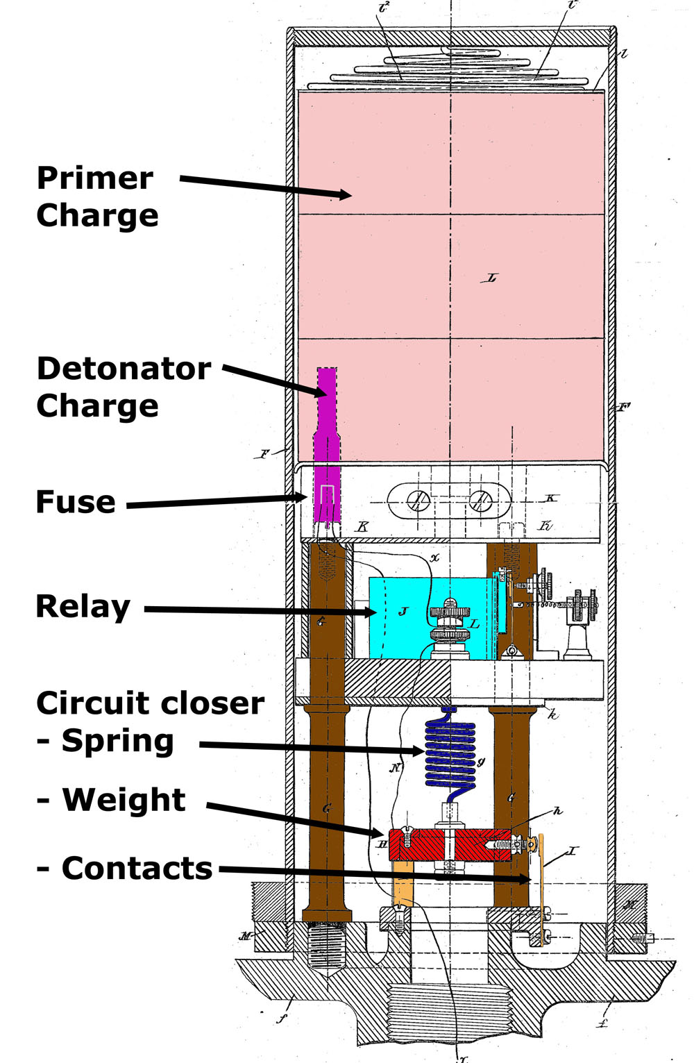
This diagram shows the various pieces of equipment. The shutter box and switches are inside the control room. The mine contains the fuse, the wooden relay and circuit closer; these three items along with the primer charge, are contained a steel cylinder called “the apparatus.”
A single cable connects each mine to an individual shutter box, with the return path through the mine’s casing and the surrounding water to an earth connection at the control station.
All of this equipment allows the mine to be configured in four different modes.
1. Test – check the integrity of the cable and the electrical components in the mine
2. Safe – the mine would not explode, even when struck by a passing ship.
3. Live – the mine would explode if struck by a passing ship
4. Detonate on observation – the mine was exploded from the control station
Test mode
– this version is from 1884 – US Patent 330,226; GB patent 11,886 .
The main component involved in testing the electrical connection to each mine was the wooden relay (a test electromagnet.) It was a rather clever non-linear device.
This relay used to use two sets of coils arranged like this: The first set of coils uses very fine copper wire, and so creates a high resistance to the flow of electricity (2000 Ω). These coils are connected directly.
The second set of coils uses thicker copper wire, creating a low resistance path (5 Ω). This second set of coils is connected through the magnetic switch.
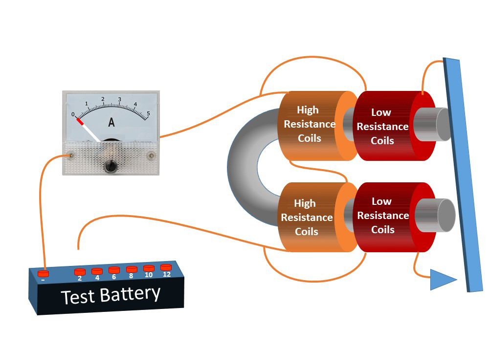
When a low voltage is applied from the test battery, a small amount of current flows through the high resistance coils as indicated on the ammeter.
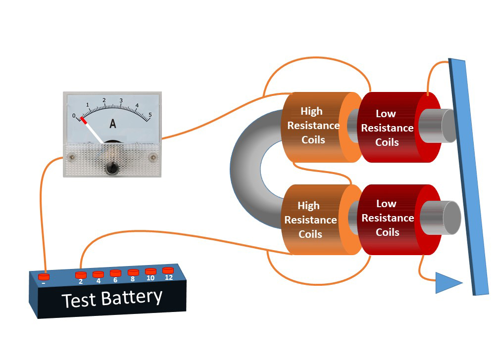
This current creates a weak magnetic field which is insufficient to close the magnetic switch.
As the test voltage is gradually increased, more current flows through the high-resistance coils, creating a stronger magnetic field.
The current passing at each test voltage is noted . . . and the test voltage is steadily increased.
Eventually the test current generates a strong enough magnetic field to close the magnetic switch and connect the low-resistance coils.
A much larger current then flows from the battery . . .
. . . as indicated on the ammeter.
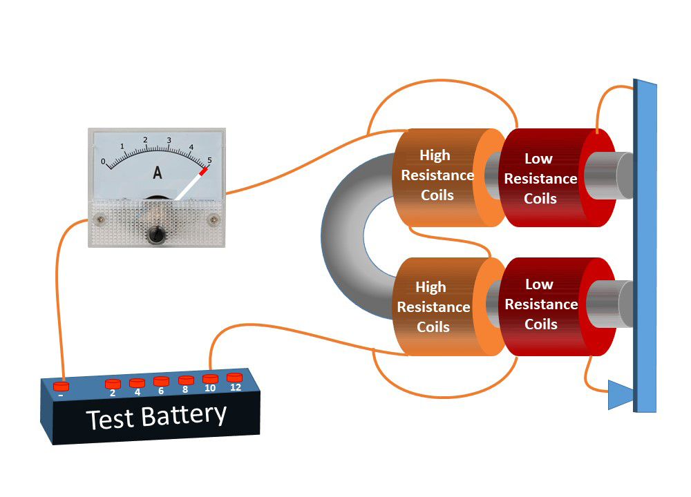
To test the connection to each mine, a test battery and a galvanometer (a sensitive ammeter) was connected to the cable running to that mine. If everything was correct, galvanometer would show a low current passing through the high-resistance coils, increasing steadily as the test voltage was increased, until the current jumped to a much higher level when the magnetic switch closed, and the low-resistance coils were connected in parallel.
If a cable had been broken and was open-circuit, no current would flow.
If the cable insulation was damaged, then a steady current would flow through the damaged insulation and back to the battery, without reaching the mine. The magnetic switch would not be closed, so there would be no jump in the level of the test current.
Both the low-level and high-level test currents flow through the fuse in the mine, but the current produced by the test battery is insufficient to heat up the fuse.
The Circuit Closer
The third piece of electrical equipment inside the mine was the circuit closer, a switch which was closed if the mine was bumped by a passing ship. This was termed an electro-contact mine or EC.
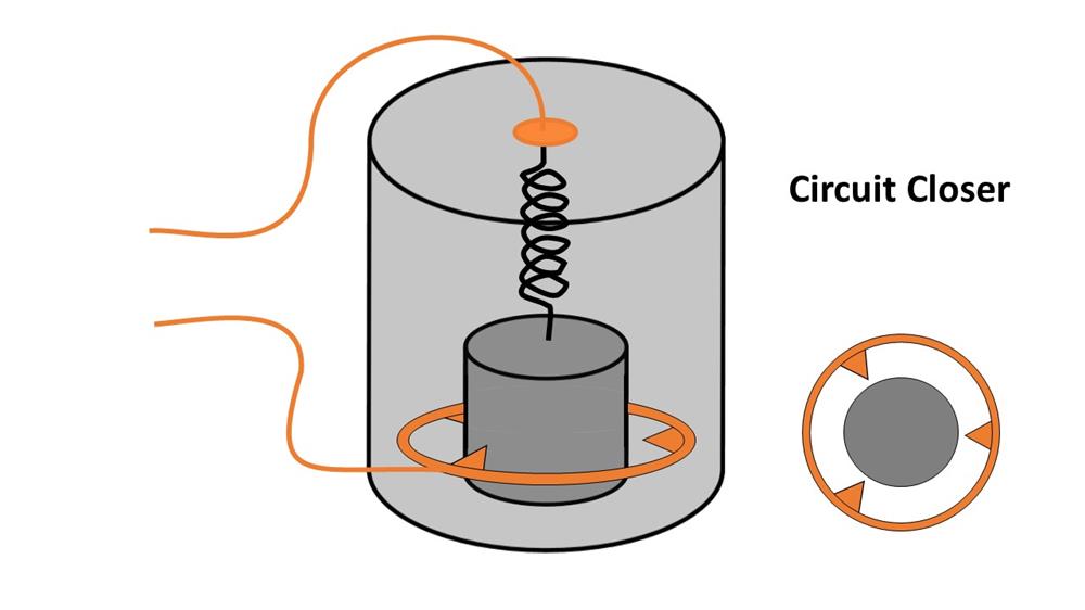
The circuit closer contains a large weight, suspended from a stiff spring.
The weight is surrounded at a short distance by a ring which carries several sets of electrical contacts.
If the mine is struck firmly, the weight will swing far enough on its spring to touch one of the contacts on the ring.
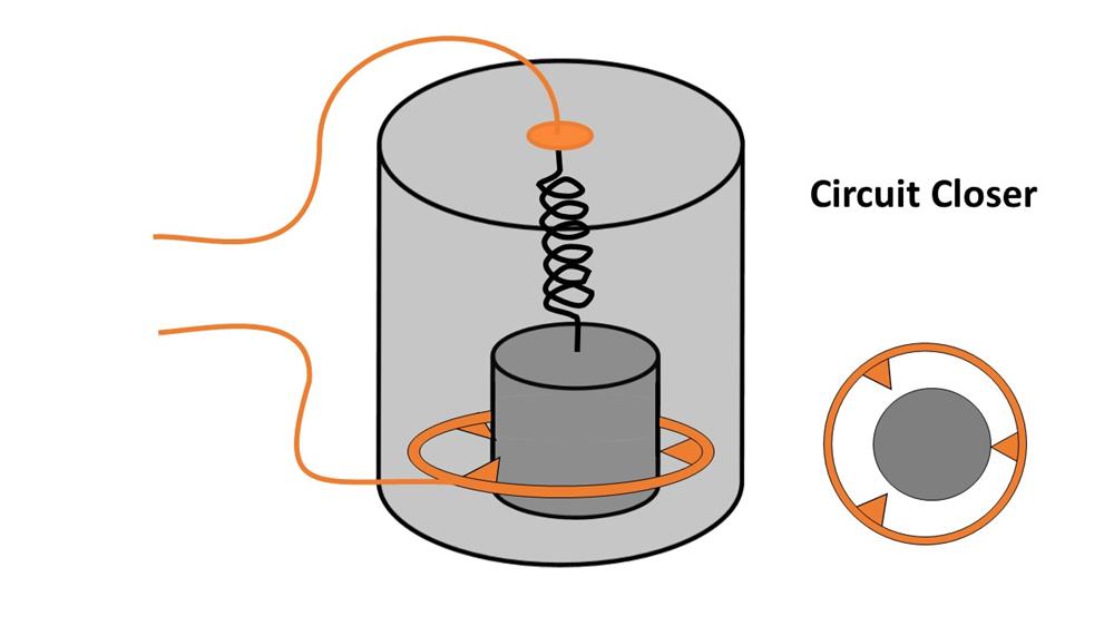
This makes an electrical connection.
However, this is only a momentary connection, which is then broken when the weight swings back on its spring.
This momentary connection does not last long enough to heat up a fuse and trigger an explosion directly. But it can be sensed by the shutter box in the shore station as described in the next section.
The Apparatus
The circuit closer, relay, fuse, detonator and primer charge were all encased in a steel cylinder called “the apparatus.” This was then fitted into the body of the mine, which contained the main charge.
Shore Equipment
The Shutter Box
The cable from each mine was connected to a “shutter box” in a pigeon-hole on the shutter board. This was a sturdy wooden board about 12 feet long by 4 feet high (3.5 by 1.2 m) mounted on solid vertical timbers a few inches away from the inside wall of the control room. This protected the shutters from the impact of exploding mines or artillery shells.
Each shutter box contains a rotating shutter. The shutter consists of one long arm and a much heavier short arm, mounted on a spindle.
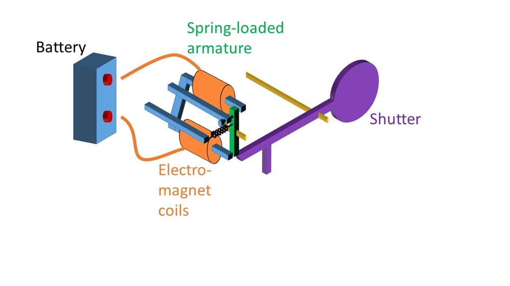
The tip of the long arm of the shutter is held in place by a spring-loaded armature on an electro-magnet.
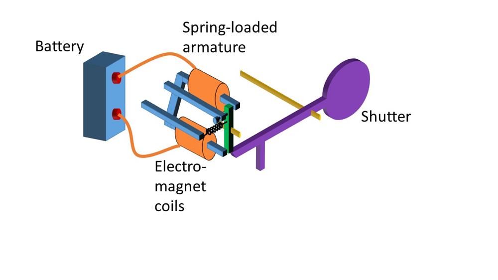
If a battery is connected, an electric current passes through the coils of the electromagnet, creating a magnetic field which attracts the armature towards the poles of the magnet.
A spring and end-stop screw are adjusted to set the level of current required to rotate the armature.
When the armature rotates, it releases the tip of the long arm of the shutter.
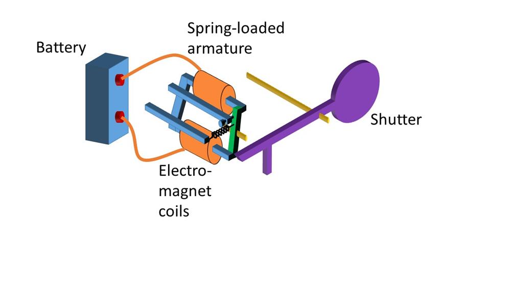
The weight of the short arm of the shutter then swings the shutter into a vertical position.

Once the shutter arm has been released, the shutter swings to the vertical position, even if the current is disconnected. So it reacts to even a momentary connection.
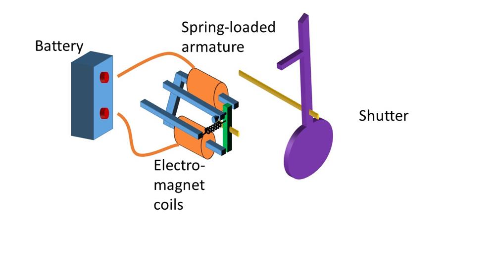
If the mine is bumped, and the circuit closer operates momentarily, the shutter box reacts immediately. A shore station observer can then see that a
particular mine has been struck.
Shutter Box Switch
As well as giving a mechanical indication that a mine has been struck, the shutter box also acts as a change-over electrical switch.
The long arm of the swinging shutter has a side leg which dips into a small bath of mercury. This makes an electrical connection from the mine, through the shutter box coils to the signalling battery.
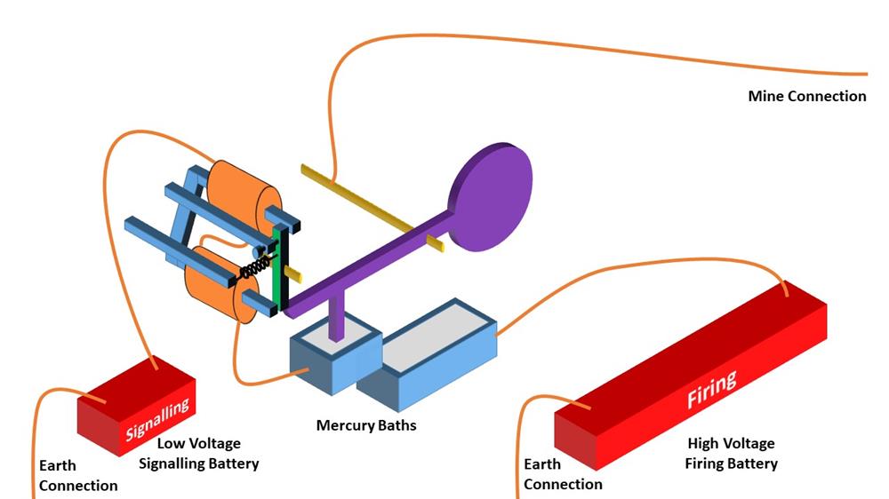
If a mine is struck, the circuit-closer switch closes, and current flows from the signalling battery through the shutter box coils, turning the armature and releasing the shutter arm.
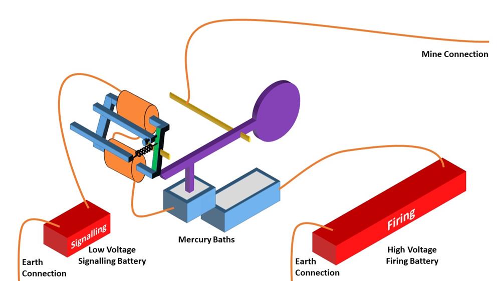
As the shutter arm swings to the vertical position, the long arm lifts out of the first mercury bath, disconnecting the signalling battery.
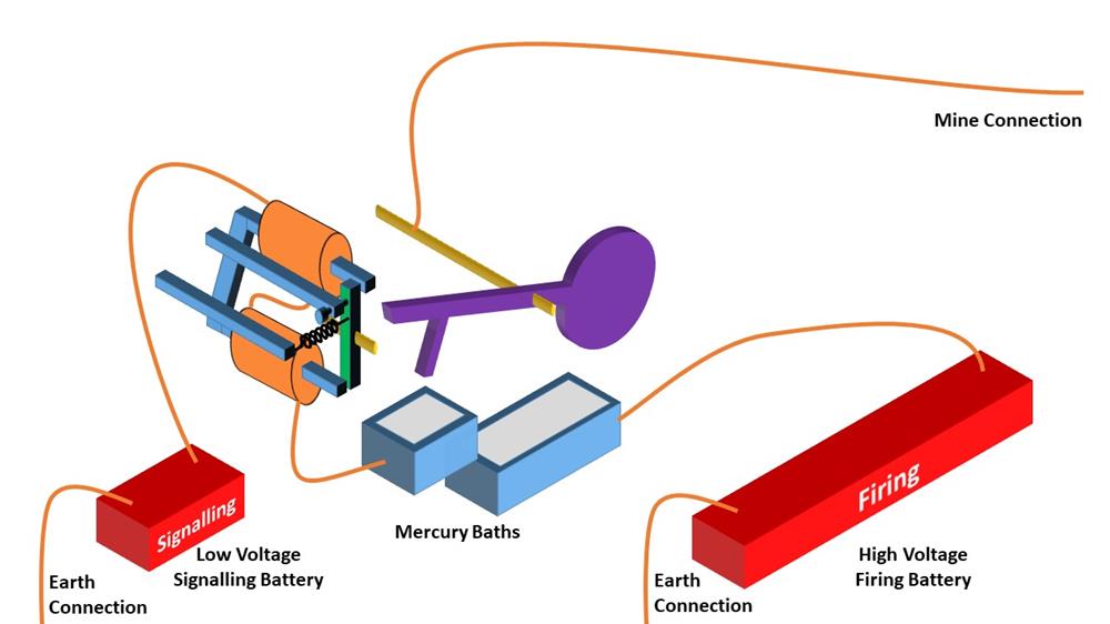
When the shutter reaches the vertical position, the short arm dips into a second mercury bath.
The shutter arm, and the cable to the mine are now connected to a high-power firing battery.
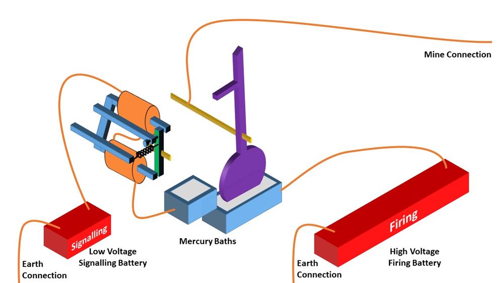
So the shutter box turns the momentary closure of the contact closer caused by a bump on a mine into a permanent connection to the high-voltage firing battery.
The complete system
This diagram shows all the components for one mine, which is configured to explode on impact.
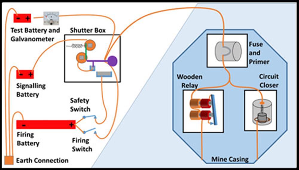
The test battery is disconnected.
The safety switch is closed, connecting the firing battery to the shutter box second mercury bath.
The signalling battery is connected through the coils of the shutter box, through the mine cable, through the fuse, through the high-resistance coils of the wooden relay, and back through the earth return path. A low-level current is flowing through this path, but the combined resistance of the shutter-box coils and the wooden-relay high-resistance coils means that this current is insufficient to close the contacts of the wooden relay, or to operate the armature on the shutter box. It is much too weak to heat up the fuse in the mine.
The sequence of events leading to detonation of the mine
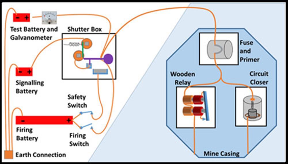
1. Everything is ready
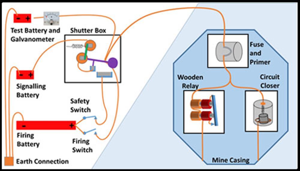
2 A passing ship has “bumped” the mine, causing the circuit closer weight to swing and touch the surrounding ring.
This shorts out the wooden relay coils, so a higher level of current now flows though the shutter box coils.
This current produces a magnetic field strong enough to overcome the force of the restraining spring, and attracts the armature, releasing the shutter arm.
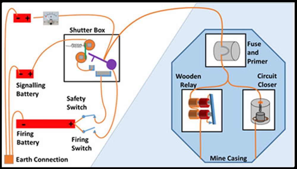
3 The shutter arm swings towards the vertical position.
The signalling battery is disconnected, and the shutter armature springs back.
The circuit closer weight can swing back to neutral – its work is done.
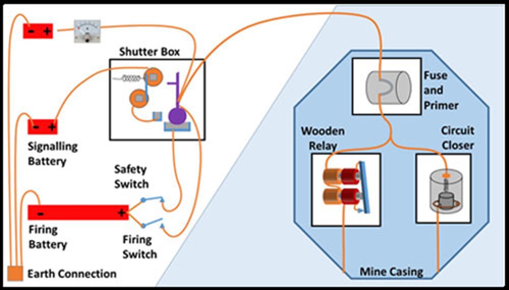
4 The shutter arm reaches the vertical position, and dips into the second mercury bath.
The high-power firing battery is now connected to the mine cable.
A higher-level current flows through the fuse and the high-resistance coils of the wooden relay
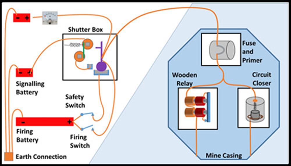
5 This current immediately closes the contacts on the wooden relay, bringing the low-resistance coils into the circuit.
The current then jumps to a very high level, driven by the high power battery through the fuse and the low-resistance coils of the wooden relay.
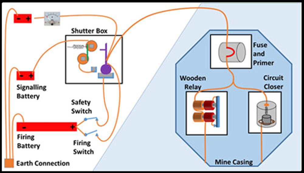
6 The platinum fuse is heated up by the very high-level current until it glows red hot . . .
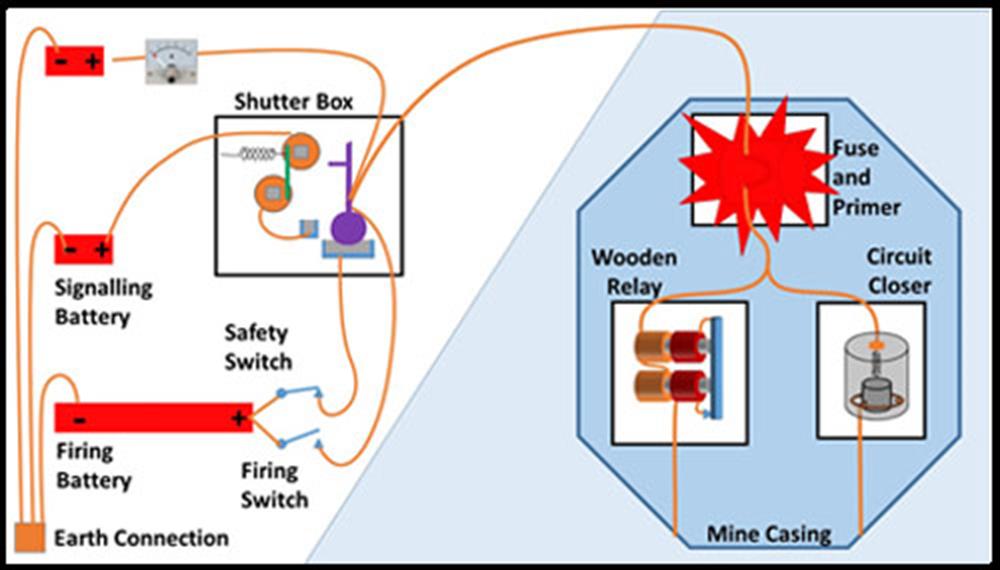
7 . . . and ignites the detonator charge, and the surrounding primer charge.
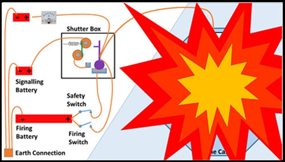
8 The main charge ignites and the mine explodes.
The Polarized Relay design
The earliest form of Electro-Contact mine, as described above, used a momentary-action contact-closer in the mine (i.e. the switch was only closed for a moment when the mine was bumped) and needed a dedicated cable to connect each mine to its associated shutter box in the shore station.
A later version used a “polarized relay” in the mine. This acted as a “latching switch” i.e. when the mine was bumped, the switch closed, and stayed closed. This new design allowed four mines to be connected to one cable, and managed by one shutter box. It was therefore more economical, and easier to deploy – fewer cables meant lower risk of cables becoming entangled.
The Polarized Relay Apparatus
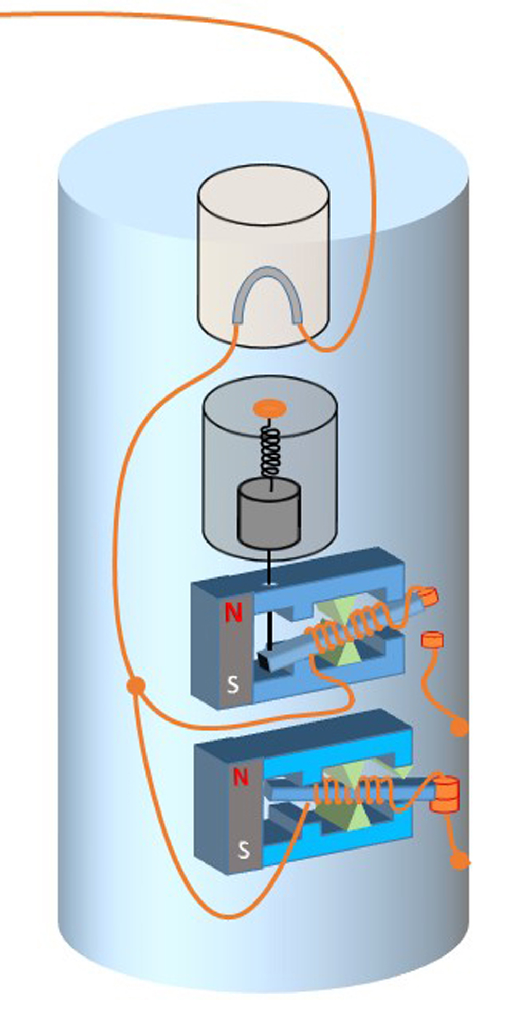
Here are all the pieces inside the mine “apparatus.”
The cable from the shore station is connected through the fuse in the mine detonator to the polarized trigger relay and a polarized test relay.
The armature of the trigger relay is in the up position, so there is no electrical connection through its 5 ohm coil to the earth return path.
The armature of the test relay is in the down position, so there is an electrical connection through its 2000 ohm coil to the earth return path. But this is a high resistance so that even if a high-voltage firing battery is connected, the current that flows is insufficient to heat up the fuse.
The circuit closer is still a heavy weight suspended from a stiff spring, but it does not have any direct electrical contacts, instead, the weight is attached to a silk thread connected to the polarized relay armature.
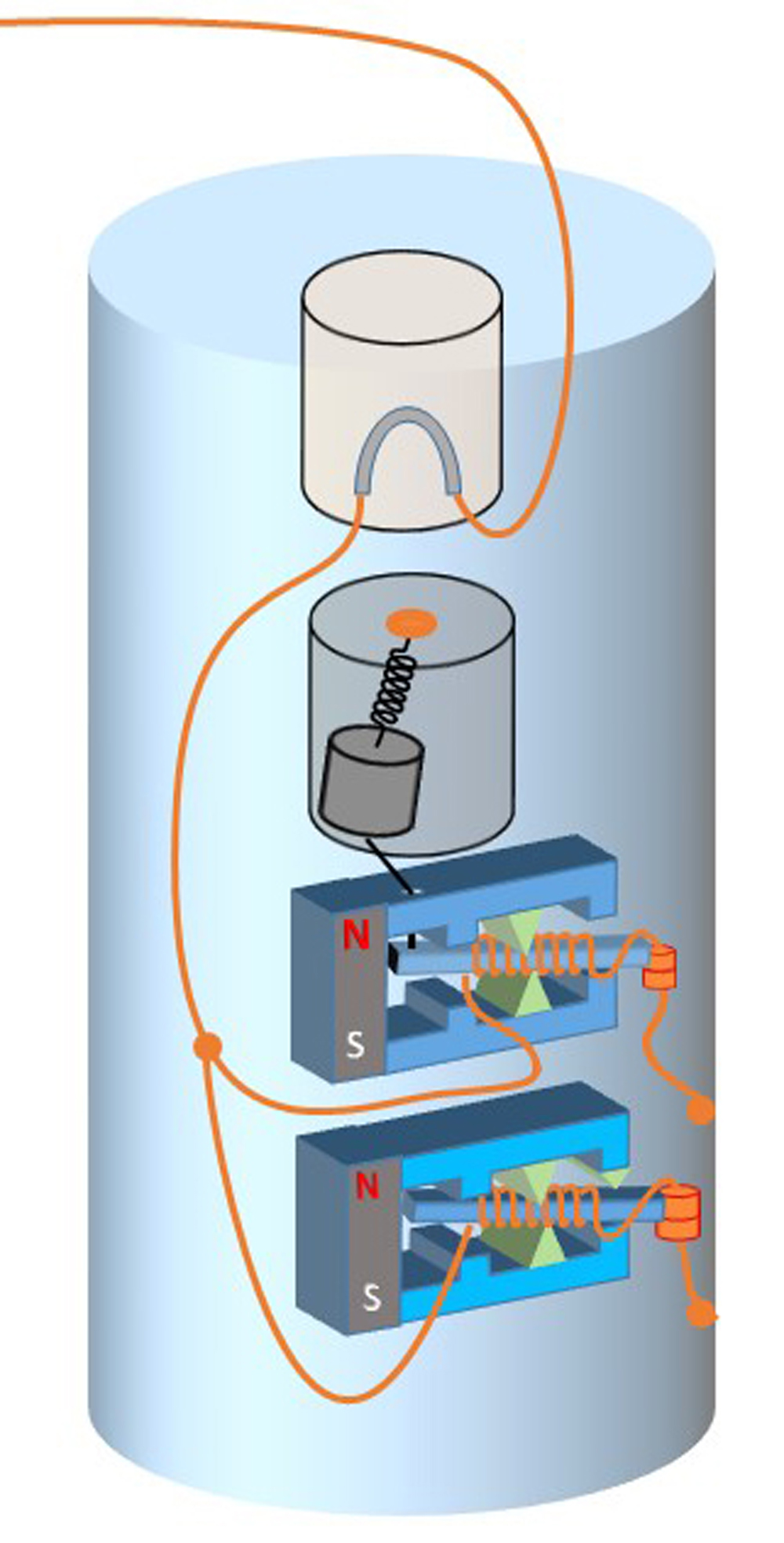
If the mine is “bumped” the weight will swing on its spring, and pull on the silk thread, flipping the armature on the polarized relay to the down position.
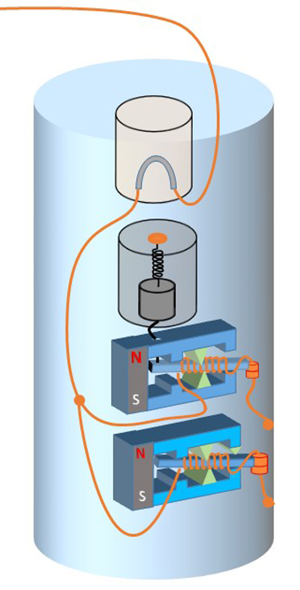
The weight will now return to its normal position, but the relay will remain in the latched condition, because the armature is attracted by the permanent magnet.
There is now a low resistance (5 ohm) connection from the fuse to the earth return path.
If a battery is connected to the mine cable, current will flow through this path.
What happens next depend on the direction of the current – determined by the polarity of the battery connection.
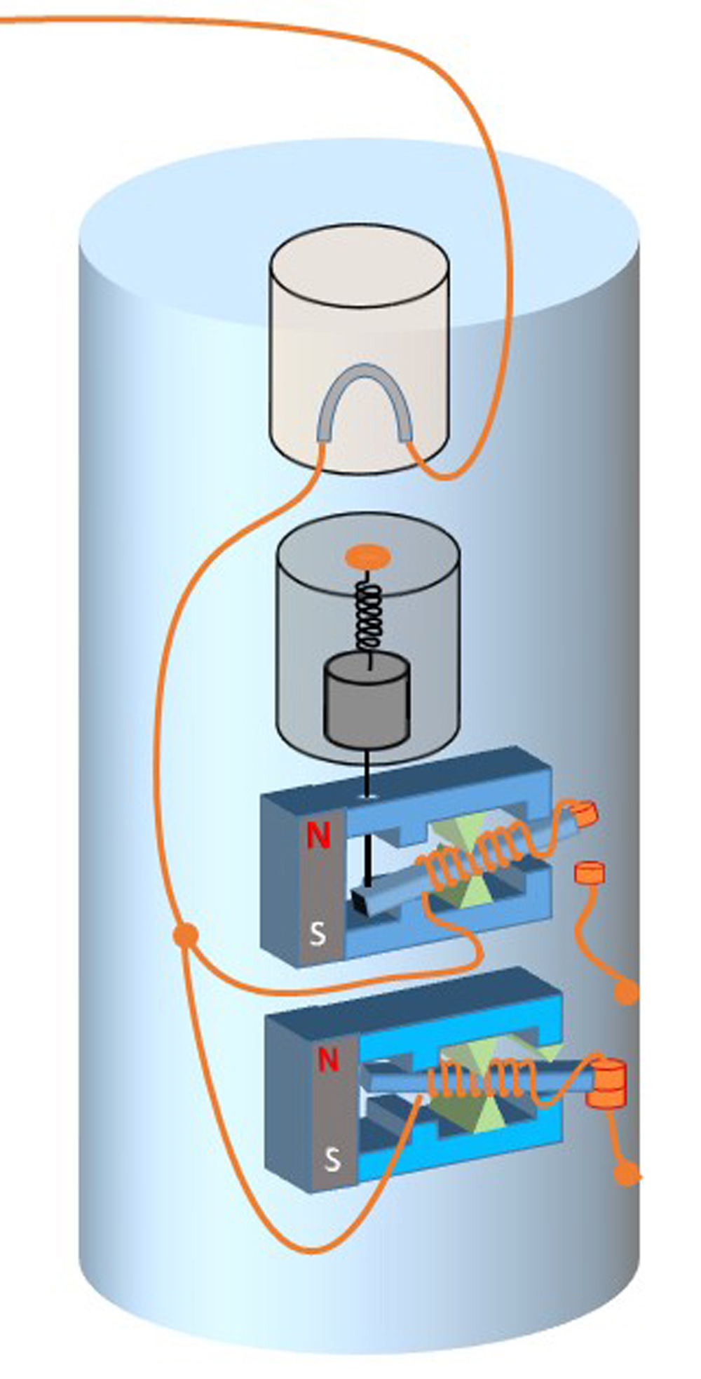
If current flows one way, the latching relay will reverse, and the armature will flip back to the safe up position. As on the left.
This is called “reversing the mine.”
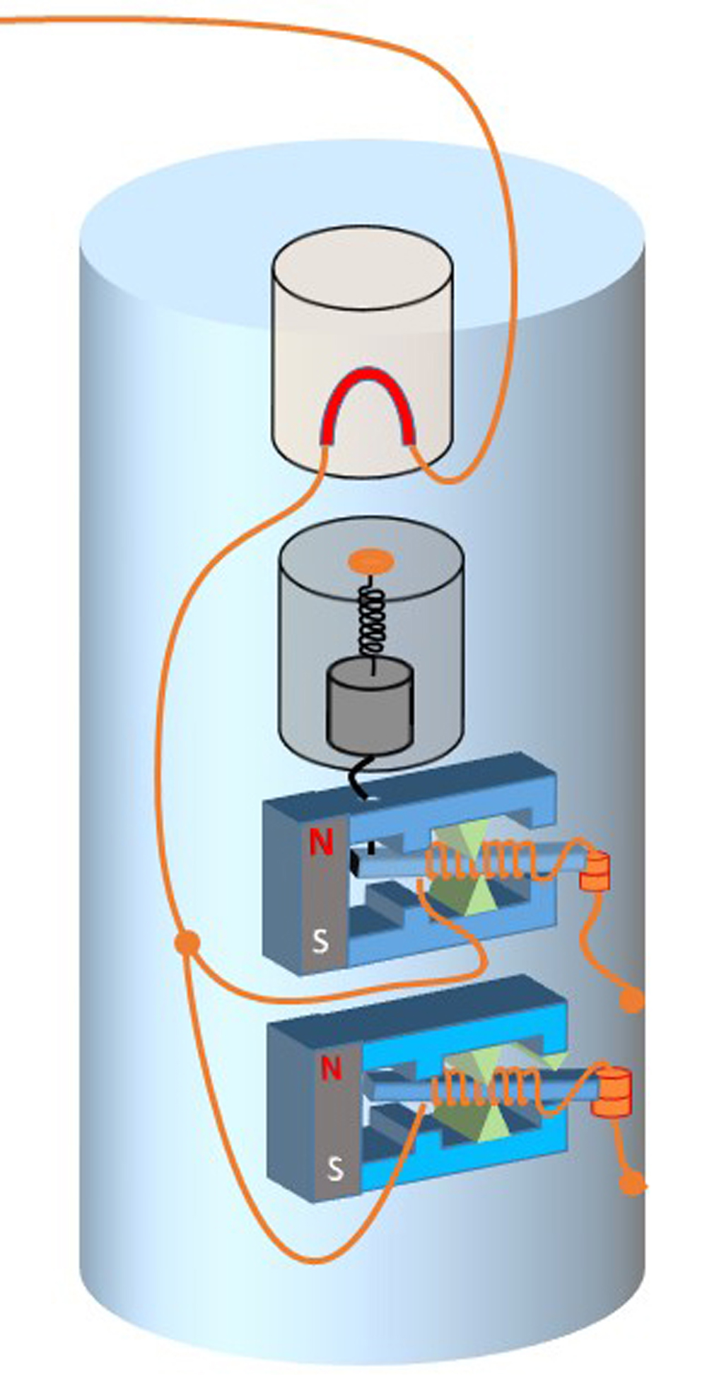
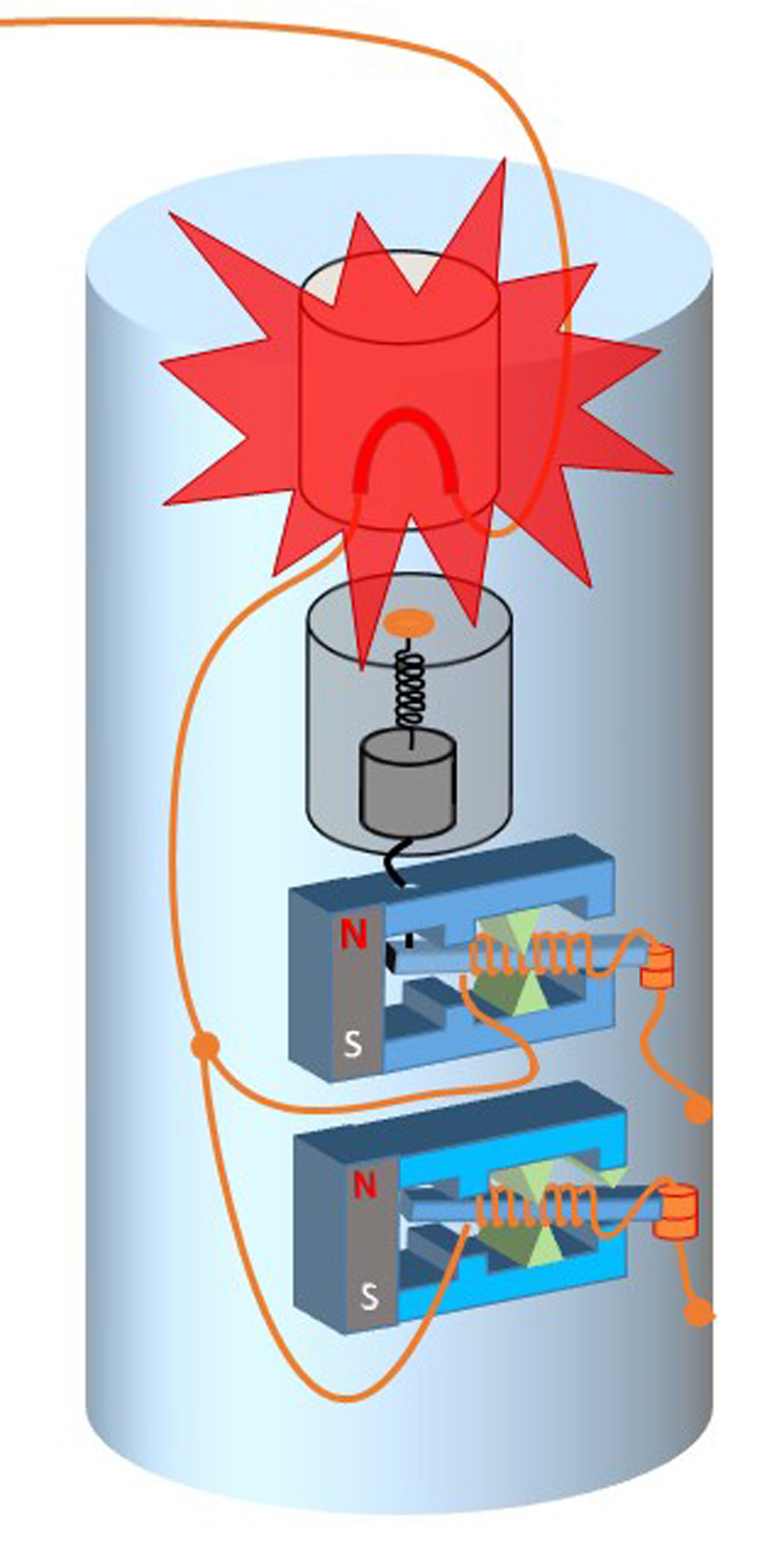
If current flows the other way, the relay stays latched with the armature in the down position, and the current heats up the fuse, as on the right, until the mine explodes.
The test relay
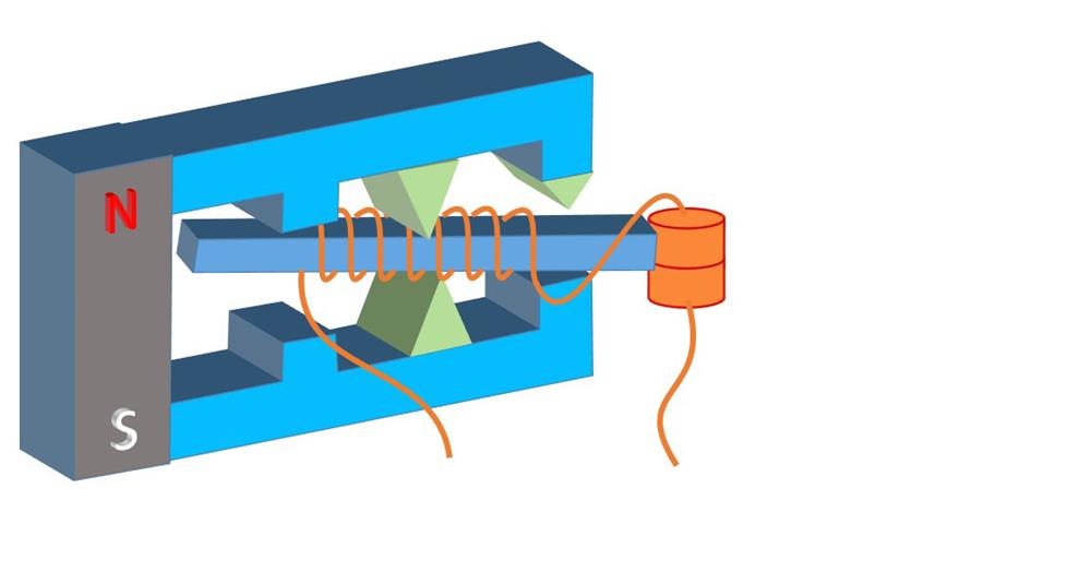
The test relay is polarized, meaning that its operation depends on the direction of the current flowing through the armature coil, i.e. it depends on the polarity of the battery connected to the cable to the mine.
In one direction, nothing happens. The current creates a magnetic field which augments the field from the permanent magnet, the armature does not move.
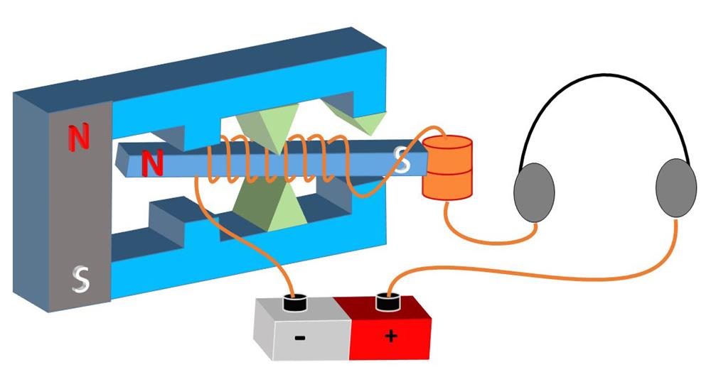
In the other direction, the relay acts as a buzzer. The electric current creates a magnetic field that opposes that pf the permanent magnet, so the armature flips up. This breaks the contact, so current stops flowing.
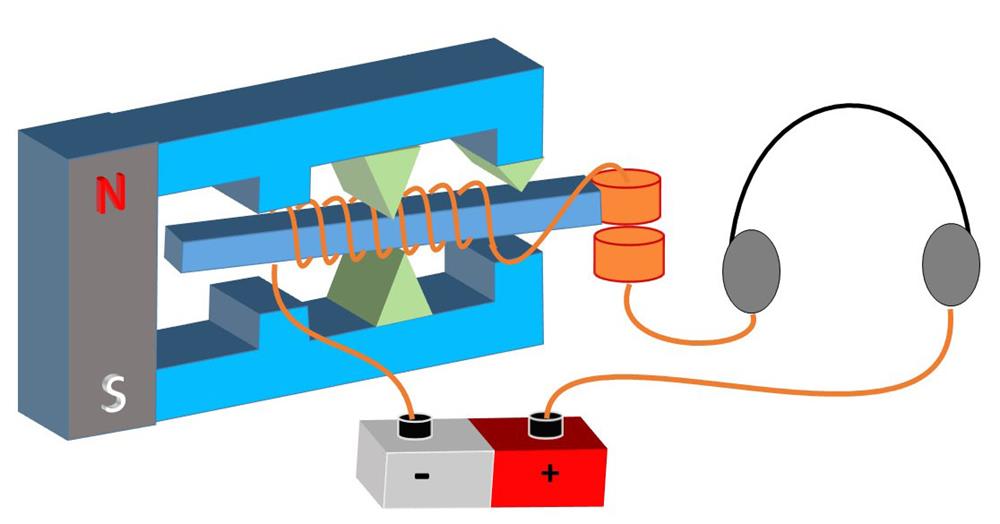
The armature is then pulled back to the down position by the permanent magnet. (A bump-stop ensures that it cannot “latch” in the up position.) This action is repeated as long as the battery is connected.
By connecting a set of headphones to the circuit, an observer in the test station can hear the buzzing action if the circuit to the mine is complete.
Connecting four mines to one cable
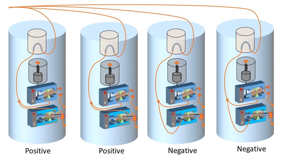
Here are four mines all connected to one common cable. All of the circuit-closer latching relays are connected the same way. However, the connections to the test relays are swapped on two of the mines. So the mines are designated as positive or negative.
They are all in the “ready” state, with the circuit closer latching relays in the up position.
If a test battery is connected to the cable, current will flow through the high resistance (2000Ω) coils in all four of the test relays. No current flows through the low resistance (5Ω) coils of the circuit closer relays – the armatures are all in the up position.
With the test battery connected with its positive end to the cable, and negative end to the earth return path, the two test relays labelled “positive” will buzz, and the observer in the shore station will hear two distinct buzzing tones in the headphones. The other two test relays will not buzz, because the current flowing created a magnetic field that adds to the field from the permanent magnet, so the armature stays in the down position.
If the connections to the test battery are swapped – negative to the cable, and positive to the earth return, then the two test relays labelled “negative” will buzz, and the two positive relays will remain silent. So once again the observer hears two distinct buzzing tones.
If the cable to any one of the mines is broken, the operator will only hear two buzzing tones with the test battery one way round, and only one buzzing tone with the test battery the other way round.
If the insulation on any of the cables is damaged, exposing the core to sea water, this will act as a short circuit, and none of the test relays will buzz, regardless of the polarity of the test battery.
Finally, if any of the mines is “bumped” flipping the armature in the contact-closer relay, then that mine, and only that mine, can be fired or reversed from the shore station.
Being able to connect four mines to one shore cable made the whole process more economical, and the deployment of the minefield was much faster.
The Compete Polarized Relay System
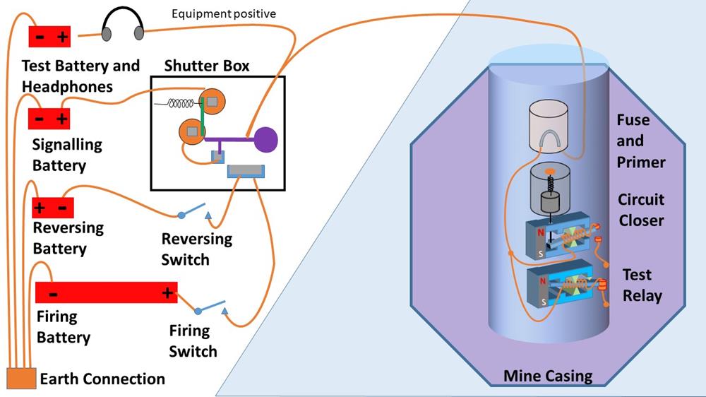
Here are all the components connected together. As before, in the signal room we have a shutter box, with a signalling battery and a firing battery. We have added a test battery and headphones, and a reversing battery and reversing switch.
The cable from the shutter box is connected through the fuse in the mine to both the polarized relay and the test relay.
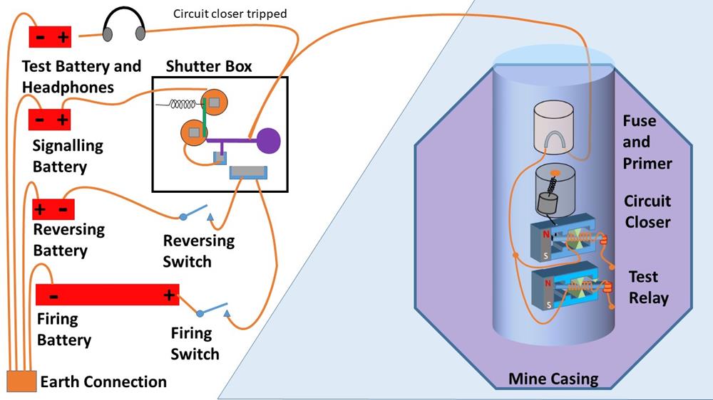
This mine has been bumped, the circuit closer weight has pulled the silk thread, and the latching relay armature is now in the down position. So there is a low-resistance connection through the cable to the shore station.
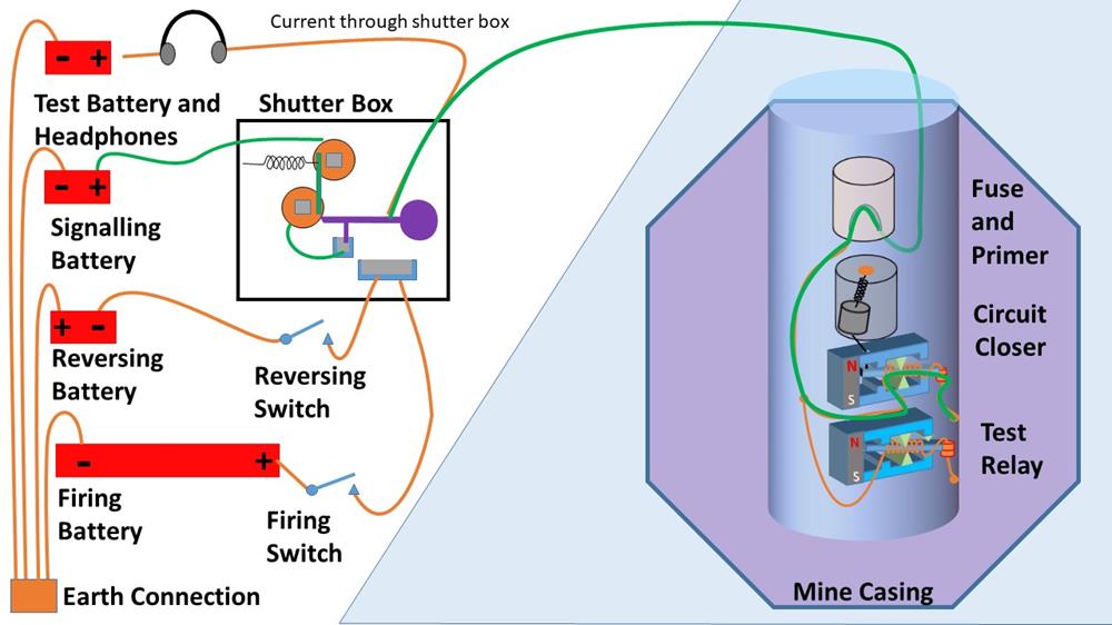
Current from the signalling battery flows through the coils of the shutter box.
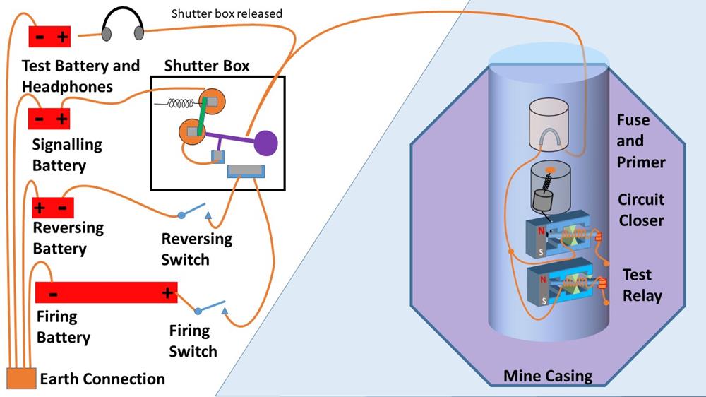
The shutter box armature is pulled against its retaining spring, and the shutter arm is released.
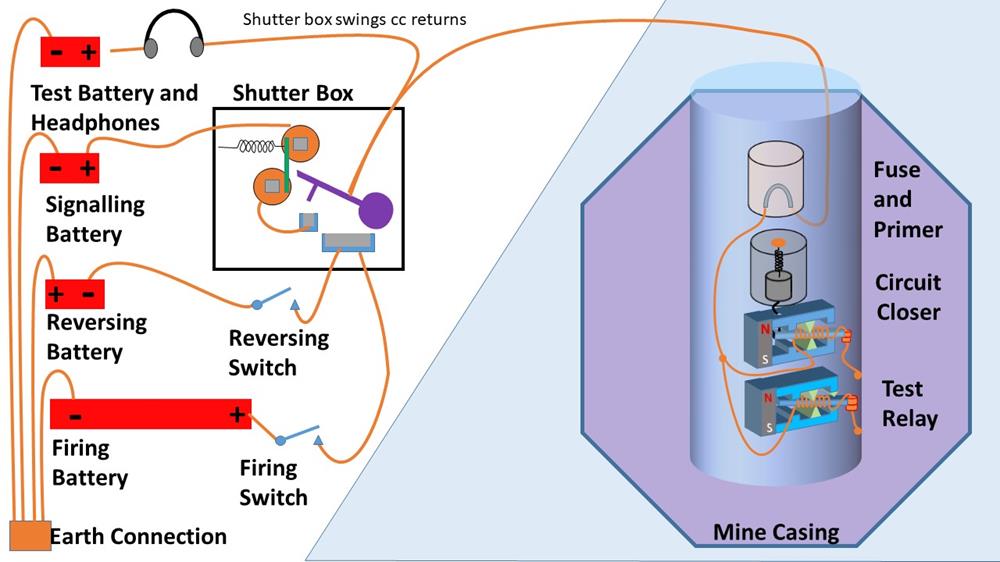
The shutter arm swings to the vertical position, breaking the connection to the signalling battery
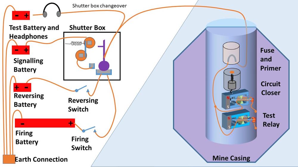
The shutter reached the vertical position, and the shutter arm is now connected to the second mercury bath connection.
The observer in the shore station sees that a mine has been triggered, and can now decide to either reverse the mine, because it has been bumped by a friendly ship, or to fire the mine.
Reversing the mine.
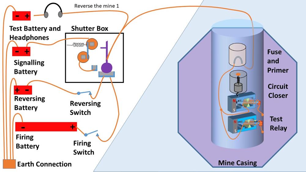
To reverse the mine, the operator closes the reversing switch. This connects the low-voltage reversing battery to the mine cable.
Current then flows through the cable through the mine fuse and through the low-resistance coils of the circuit closer relay. Although this is a low resistance path, the current driven by the low-voltage reversing battery is not enough to heat up the fuse in the mine.
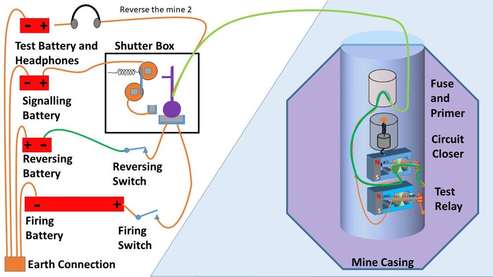
This current flips the circuit closer relay back to the up position. The mine has been “reversed” and is back in the ready state.
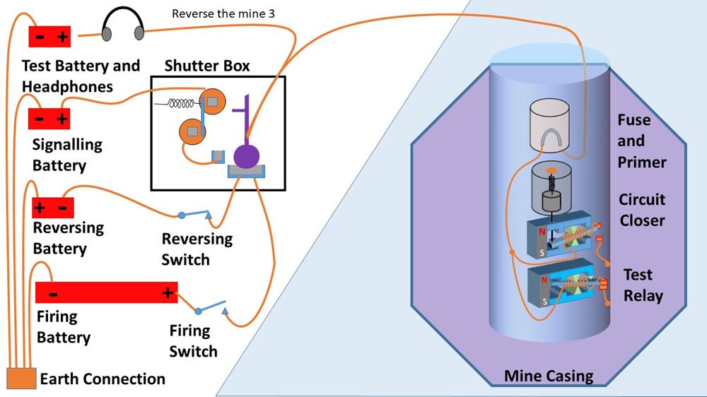
The operator then opens the reversing switch, and manually swings the shutter in the shutter box back to the horizontal position.
Firing the mine.
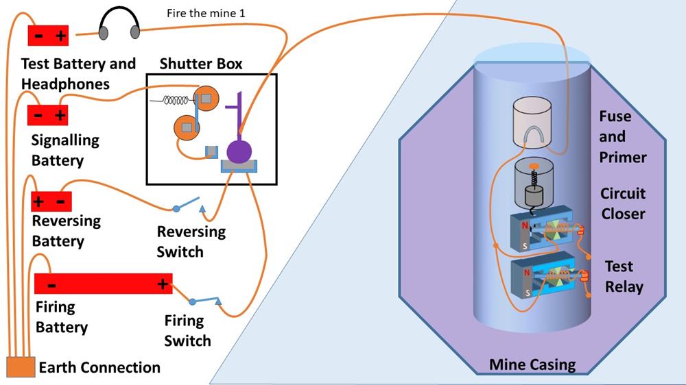
To fire the mine, the operator closes the firing switch, which connects the high-voltage firing battery to the cable
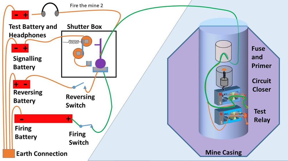
Current flows through the cable, through the fuse and through the low-resistance coils of the circuit closer relay. The direction of this current through the coils creates a magnetic field which adds to the field of the permanent magnet, so the armature remains in the down position, and a high current driven by the high-voltage firing battery flows through the fuse and the circuit closer relay.
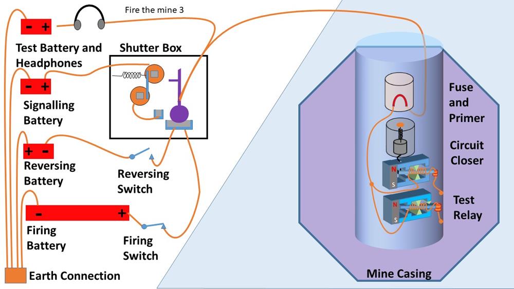
The fuse heats up, becomes red-hot . . .
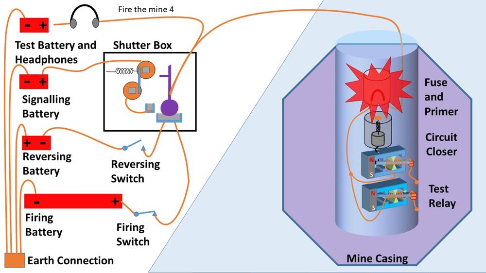
. . . and ignites the primer charge –

This ignites the main charge and the mine explodes.
Some subtleties
The test relay once the mine has been bumped.
The test relays remain in circuit in all the mines at all times, regardless of the state of the circuit closer relay.
They will buzz or stay latched when the signalling battery or firing battery is connected to the common cable to a group of mines (depending on whether the test relay is wired “positive” or “negative.” But the test relay has a high resistance coil (2000 Ω) so very little current flows through the test relay, not enough to heat up the fuse and trigger an explosion, even when the firing battery is connected.
The exposed mine cable after a mine has exploded
Once a mine has exploded, the tattered end of its connecting cable is now exposed to the sea water, so short circuits the connection to the remaining three mines in the group.
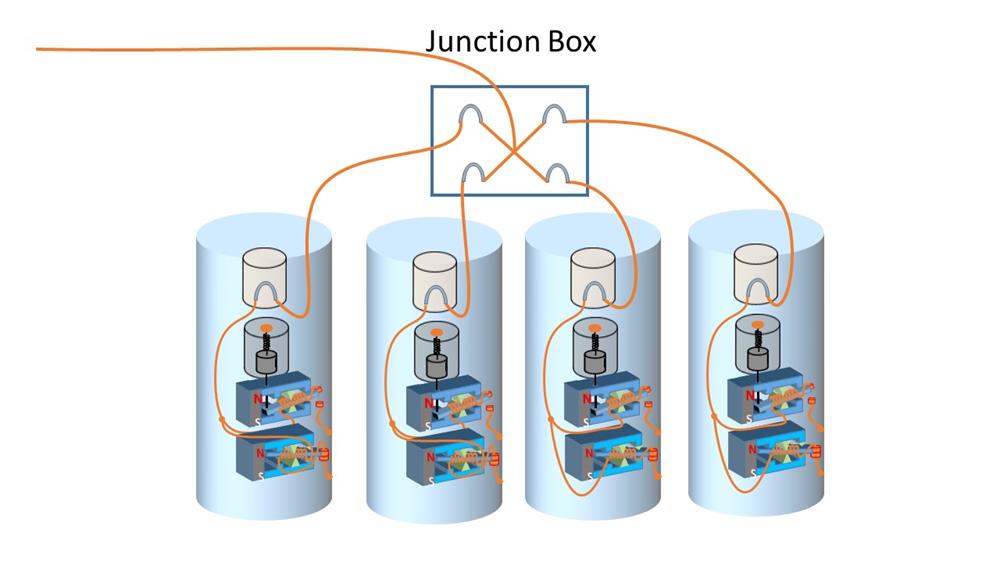
This problem is solved in the junction box which attaches each of the four mines to the shore cable. Each cables to an individual mine is connected throyght its own fuse in the junction box.
This fuse has the same characteristics as the fuse in the mine.
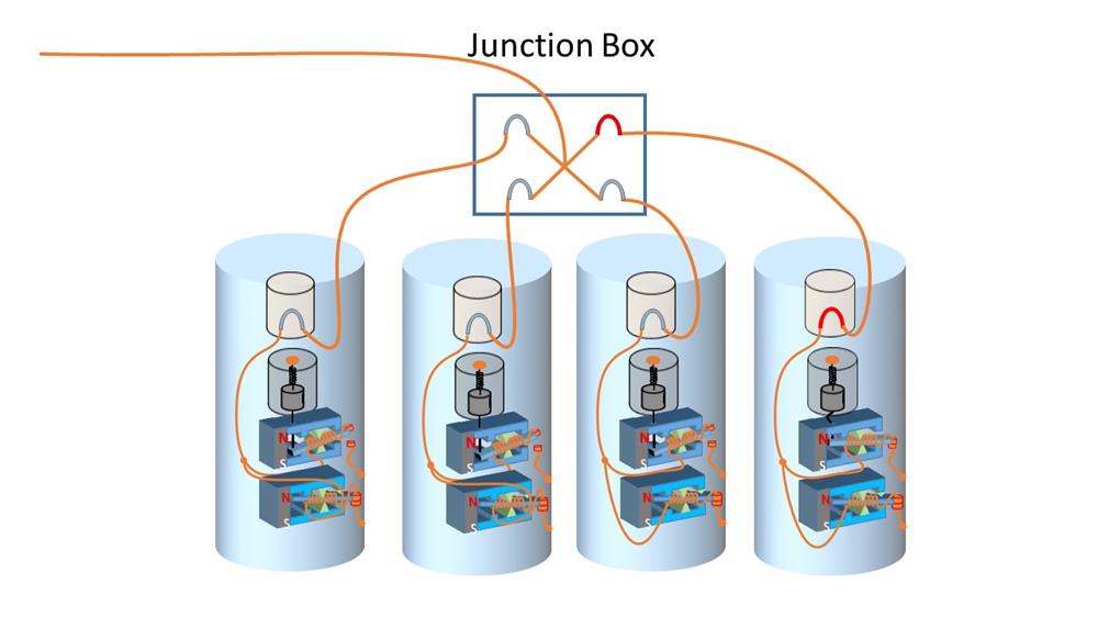
When a mine is fired, the two fuses both heat up very rapidly.
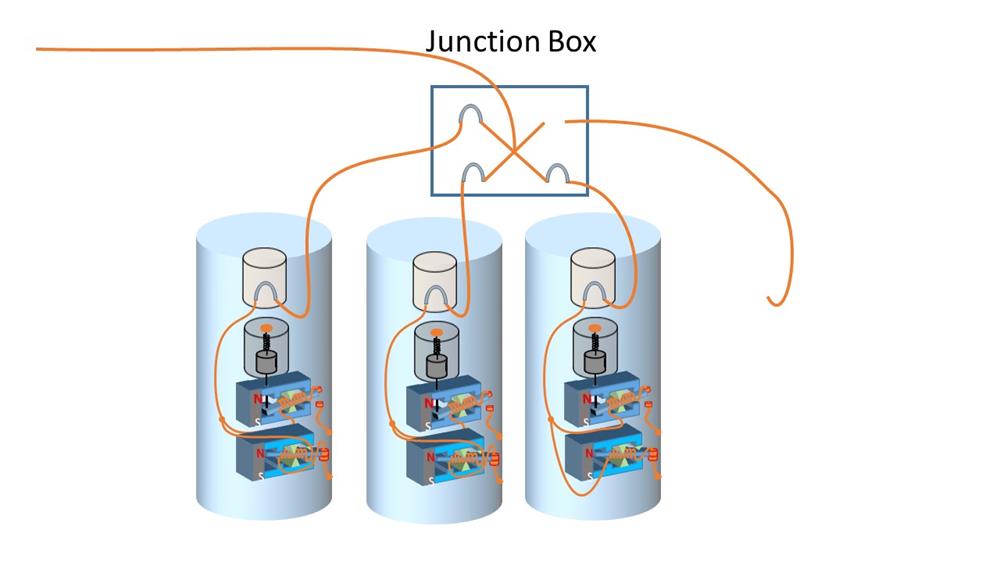
When the mine explodes, the fuse in the junction box melts at the same time, disconnects the end of the cable, and removes the resultant short circuit to the sea water.
Firing the mine by Observation
If an enemy ship attempts to sail through the friendly channel, a mine can be fired directly from the shore station.
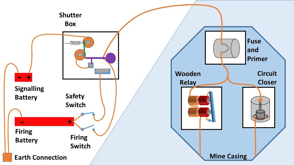
This example uses the early combined observation / contact mine with a wooden relay, but the principle remained the same as the mines evolved.
The observer simply has to close the Firing Switch.
This connects the firing battery directly to the mine cable. Current flows through the fuse and wooden relay, and things proceed from step 5 above.
The wooden relay contact closes, the fuse heats up and the mine explodes.
The trick with an observation mine is determining when an enemy ship is over the mine, which is invisible, resting on the sea bed.
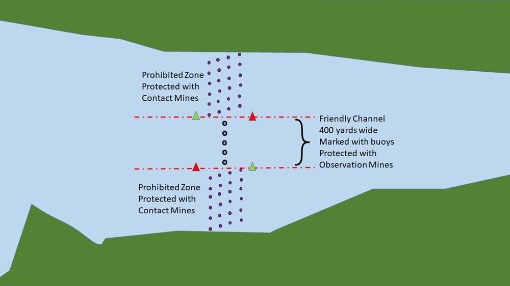
Here is a map of a river estuary, defended with a minefield.

The minefield is controlled from two observation stations.
Each if these has a sighting telescope. When each mine is laid, the bearings from each observation station are inscribed on the sighting platform. So if an enemy ship is observed at one of the intersections, the mine can be fired.
Automatic firing
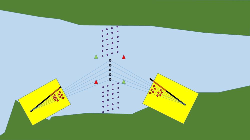
Some stations used an automatic system. An insulated metal block was attached to each sighting telescope. The bearing line for each mine was delineated by a pair of metal contacts.
When the telescope was aiming at one of the mines, the metal block made an electrical connection between the contacts.
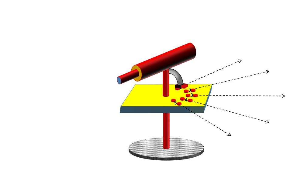
Here is a telescope with the metal block on the end of a swivel arm.
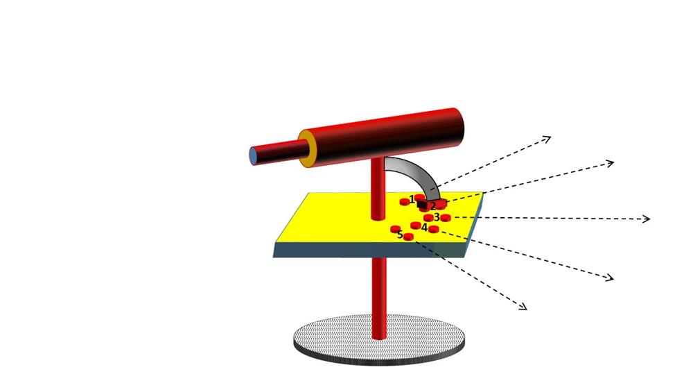
As the telescope swings round, the metal block makes contact with each pair of contacts in turn
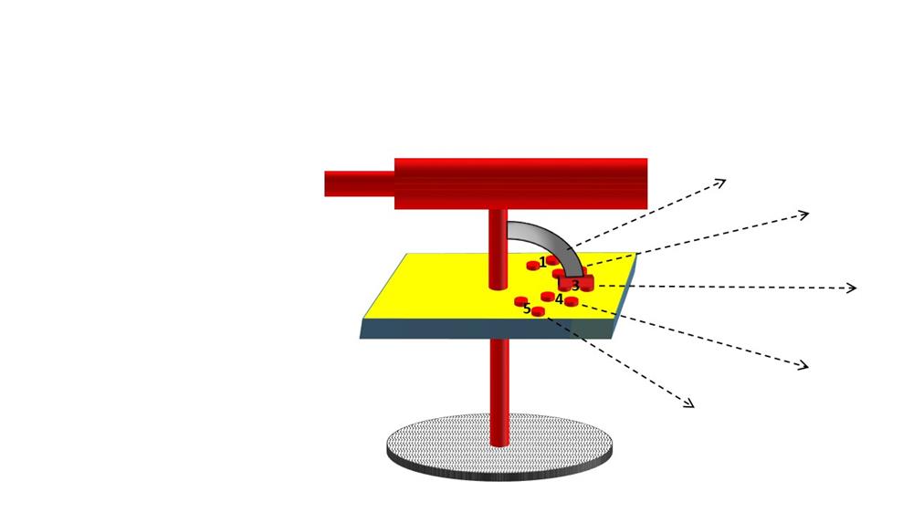
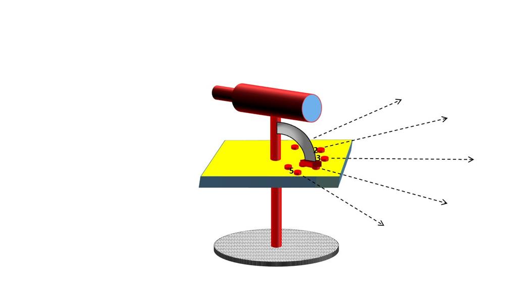
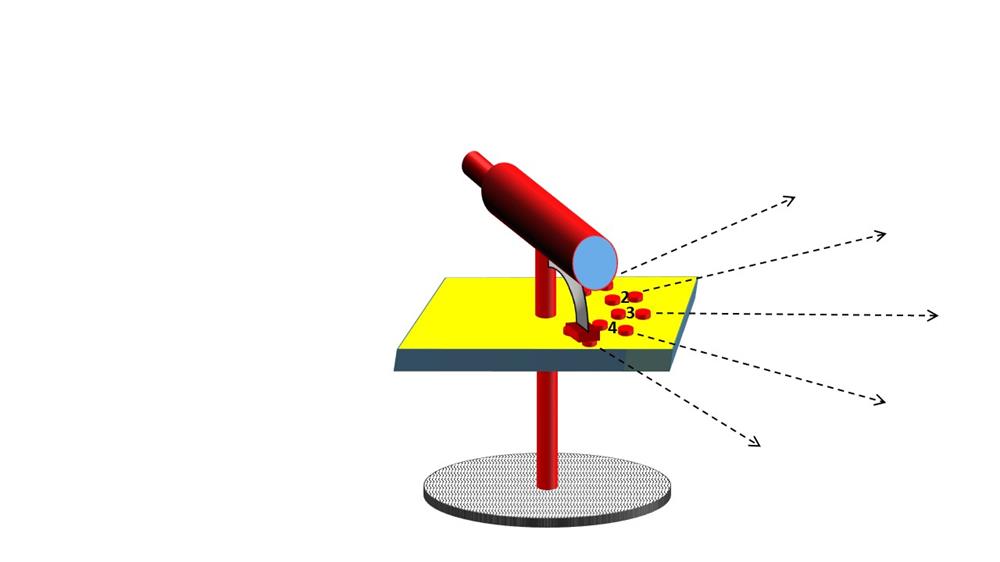
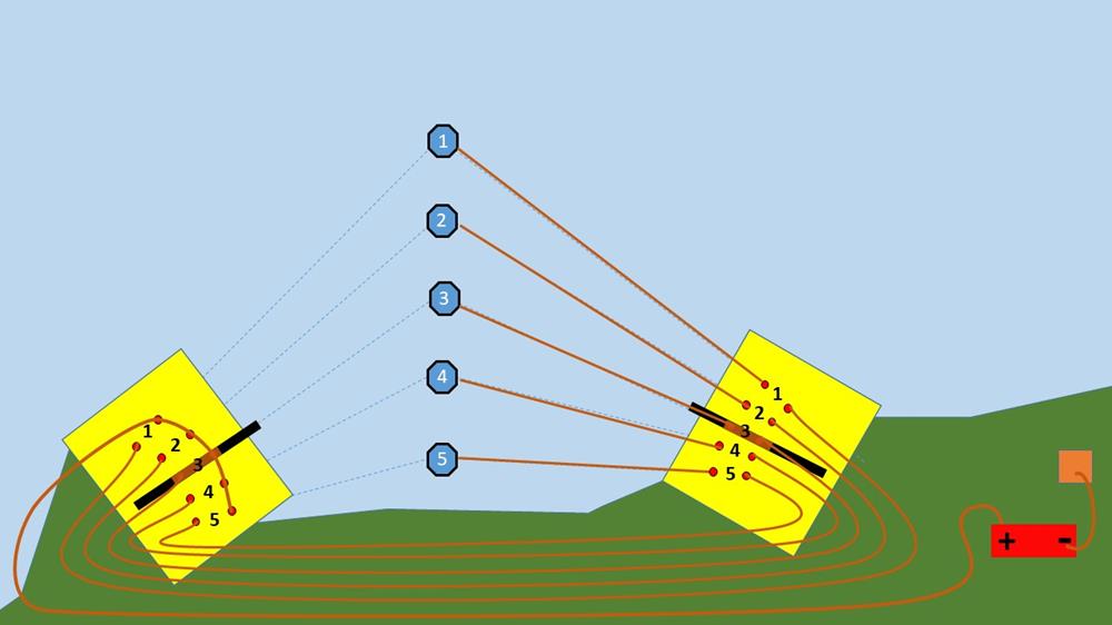
The sets of contacts at each station are connected like this.
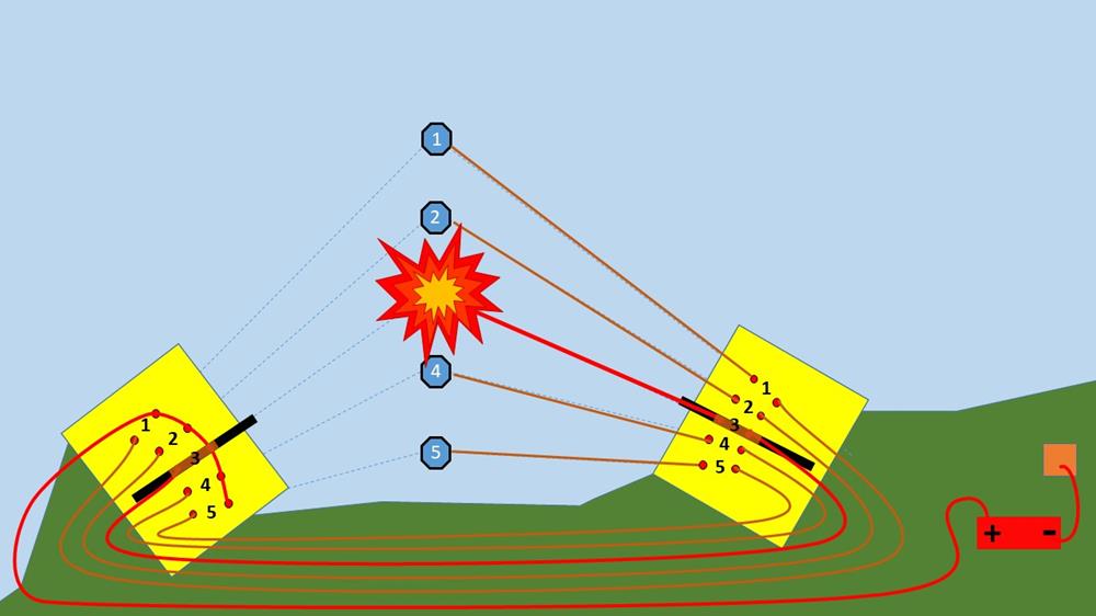 If both telescopes are pointing directly at any one of the mines, a circuit is completed which connects the firing battery to that mine.
As an enemy ship tries to sail up the estuary, it is tracked by the telescopes at both stations.
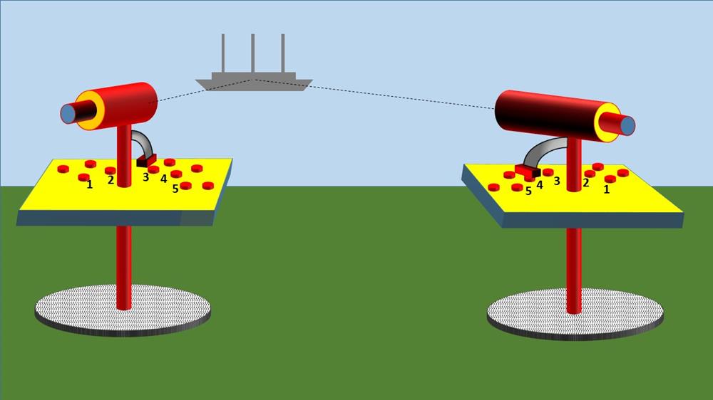
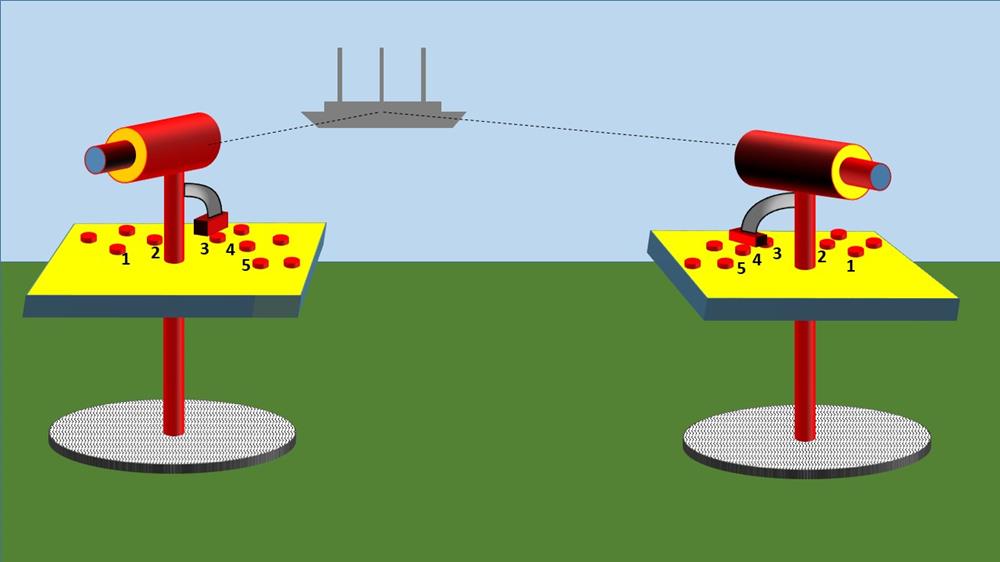
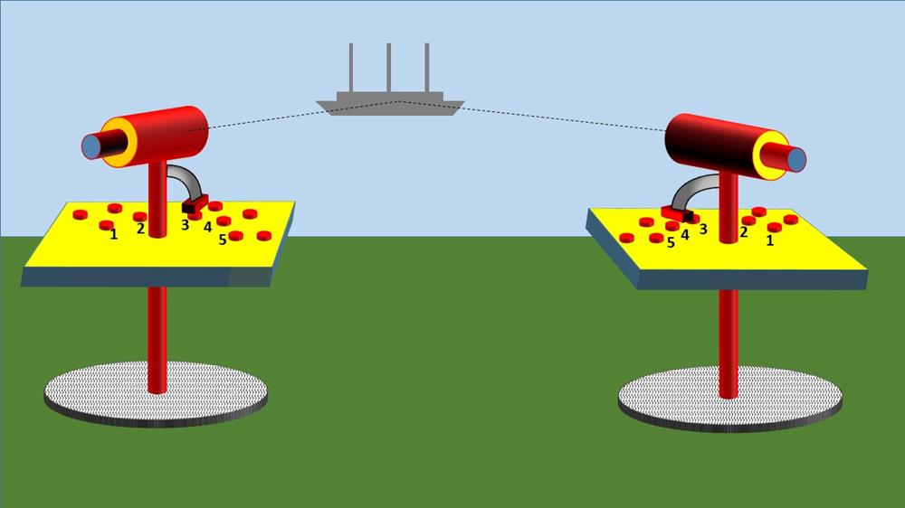
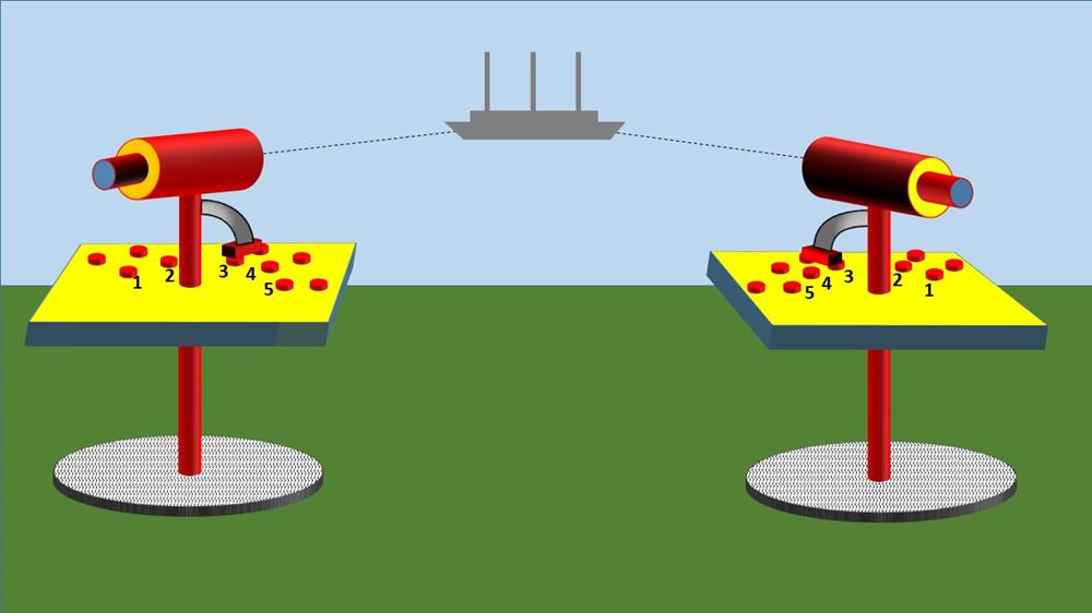
When the ship is above mine number 3, the contacts are closed on both sighting telescopes . .
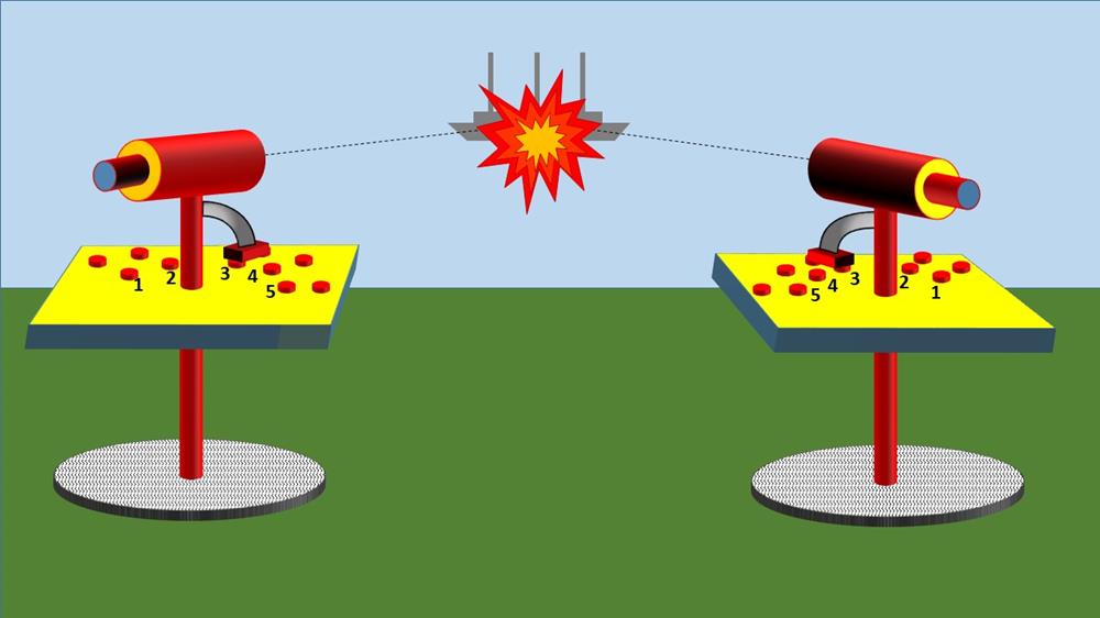
. . .and the mine explodes.
| < back to Electrical Control of a Mine | Δ Index |